Week - 4
1.Implement control logic of a" washing machine" using stateflow as per the given sequencesIf the power supply is avaliable,the system gets activated
- If the water supply is not avaliable,stop the process and indicate through LED
- Soaking time should be 200s followed by washing time of 100s
- Then rinsing happens for next20s and dryer runs for 50s
- After all the processes have been completed turn on the finished LED
SOLUTION:
.A washing machine used to wash various type of clothes without applying physical effort.With a washing bmachine,you don't have to rub the clothes with your hand or squeeze them to remove the water from them.
.The washing machine enables you to wash your clothes automatically without having to superwise the operation all you have to do is put the clothes in the machine and select the wash mode
.The washing machine automatically takes in amount water than humans judge how much detergent needs and select the mode to decide by clothes the door automatically operation started.
Stages of washing machine:
1.Prewash
2.Washing
3.Rinsing
4.Spinning
PREWASH:
.The option called prewash indicated filling the drum with a certain water level and mixing up with detergent powder.all this option helps to wash out all the stains including the stubborn or dirty very well from the clothes.This is possible as we soak the whole clothes placed into drum finally drain the water without making a second thought
.Whereas at the top load washers, there are water level sensors for filling the drum a certain level and cleaning the entire load getting rid of stubborn stains successfully.
WASHING:
.At this particular time,the machine users agitation which is for mixing both water and detergent,in turn moving the clothes all around the drum.Generally,the top load washing machines comes with an agitator or impeller placed at the center of the tub.
.While coming to front load washers,it depends upon the rotation of the entire tub provided for enhancing better wash and cleaning the load ultimately.Moreover,the duration is taken to complete the wash cycle is depends upon the settings option chosen by the users,alwaysbthe heavy load enhances high duration .Small or limited load enhances less duration
RINSING:
.The option called rinsing is known for the multi-talented option.During this particular cycle is not the flow,the soapy water is taken from the clothes.And all tge fresher or pure water is sparkled to clothes avaliable in the tub.This particular rinse option is held responsible for taking soapy water out of the washer without facing any kind of diffculties.Finally the imagination with plain water is considered of the last step in the rinsing option.
SPINNING(dryer)
.spinning is done to dry the entire clothes before getting to the end of the actual wash cycle.And these several washing machine are going to be spun at differentbspeeds.In turn,the speed of one particular spin is calculated in revolutions as per minute(rpm) respectively.This indicates the speed of the spin extracting the whole amount of water from the clothes making it dry very well.
MODELLING OF WASHING MACHINE IN SIMULINK:
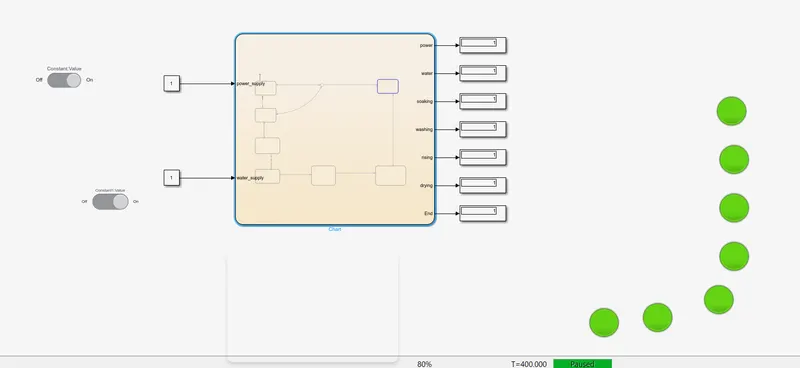
These are the following things we need for modelling the subsystems of the washing machines block setting:
1.TOGGLE SWITCH:Given to ON/OFF condition for power supply and water supply
2.CONSTANT:Given to input for power supply and water supply
3.STATE FLOW CHART:Assign your main chart and heart of our simulink washing machine
4.LAMPS:The lamp glow two colors [red-0] and [green-1] 0 is OFF and 1 is ON conditiin,lamp interconnect with display
5.DISPLAY:show the output
FLOW CHART FOR WASHING PROCES
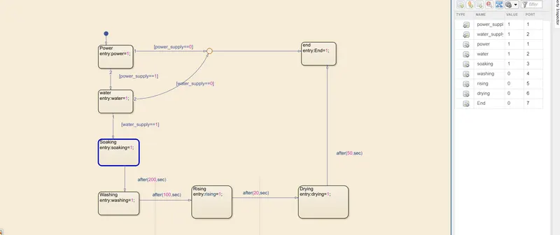
Delay times are mentioned in the questions
Simulink model of washing machine:
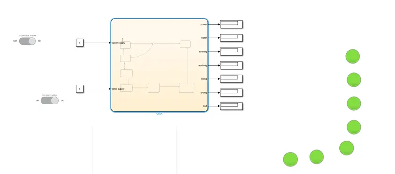
WORKING PROCEDURE:
When the power and water supply are 1 condition then the flow of program goes to next state.if the power is 1 and water supply is 0 then the process cannot continue to next step the process will end .Both inputs should be high is manadtory in our chart
Inputs are high then the soaking state will active for 200 sec,after 200 sec soaking state changes to the washing stare for 100 sec,after washing state it goes to rinsing state for 20 then it goes to drying state for 50 sec and the process will end
OUTPUT
POWER ON
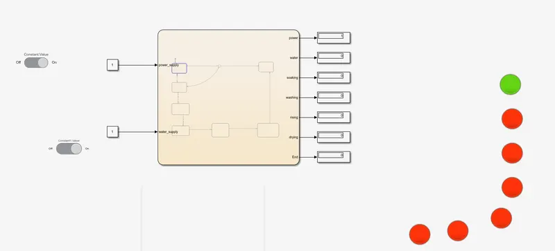
WATER SUPPLY ON
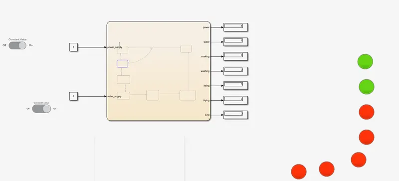
SOAKING
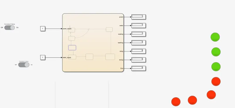
WASHING
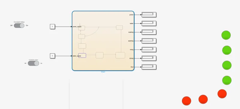
RINSING
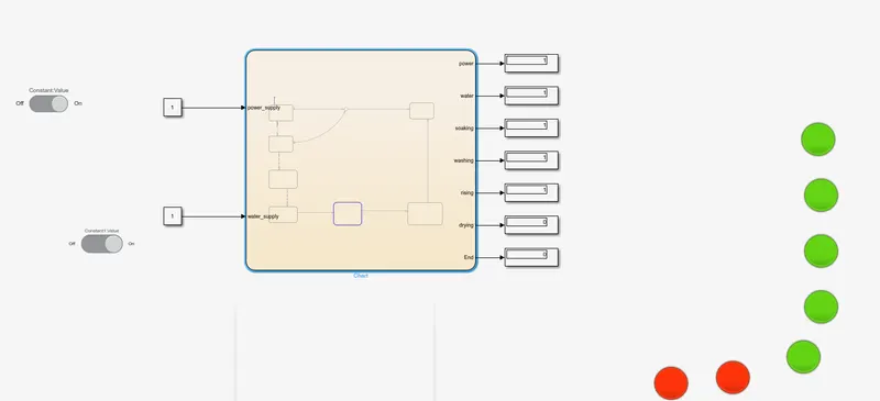
DRYING
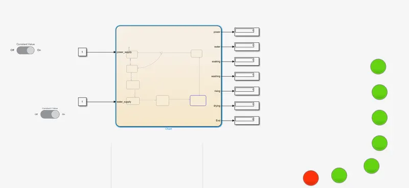
END
RESULTS
output condition shows system work as per the given condition
2.Make a simulink chart for the gear shift "logic as per the below condition:
Speed Range(km) Gear
0 to 15 1
16 to 25 2
26 to 40 3
41 to 60 4
above 61 5
Given speed input while the simmulation is running and display the gear number
SOLUTION:
The transmission operating mechanism:
.To effect the gear change,selecting first gear,for example the driver depresses the clutch,disengaging the input shaft .using the shift lever ,the divers selects the first gear, and the linkage moves the shift fork to connect the 1st-2nd locking coolar with the 1 st gear,locking it to output shaft.Now when the clutch is released,engaging the input shaft,output shaft turns because 1 st gear is locked to the output shaft by locking collar.As per the drivers speeds up,selecting 2nd gear simply involved repeating the process but moving the shift lever to 2nd gear. The shift shaft moves the shift fork to disengage 1 st gear and engage 2nd gear.Releasing the clutch engages the input shaft again this time routing power through 2nd gear.Changing to 3rd gear involves using a second shift linkage,shift fork,and locking collar,this one between 3rd and 4th gear.
Because the counter shaft and output shaft turns at different speed,moving from 1st gear to 2nd gear,trying to engage a higher gear while the vechicle is moving slower would be trying to turn the shaft at two different speeds,which is impossible.synchronizer rings are likely tiny clutches using friction to bring the locking collar and the gear to the same speed at which point they easily mesh and power can be reapplied
Before we go into the simulink for the transmission box simulates we need to follow the below conditions for setup
Speed Range(km) Gear
0 to 15 1
16 to 25 2
26 to 40 3
41 to 60 4
Above 61 5
FLOW CHART FOR SIMULINK BLOCK DIAGARAM
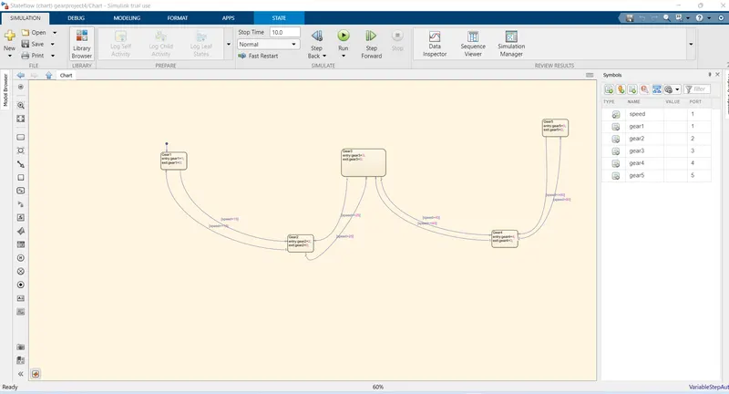
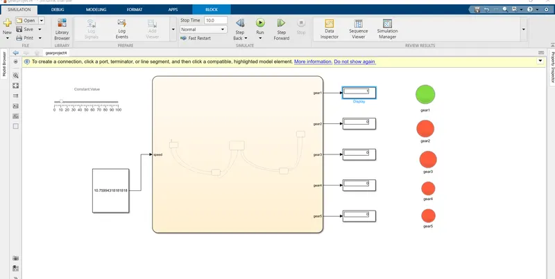
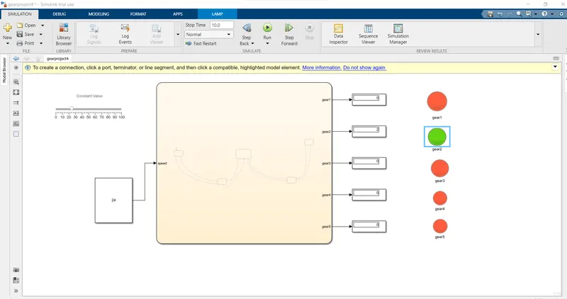
These the following block setup did we need for the setup:
.CONSTANTS:Given to input for gear system.
.SLIDER:Variable speed set in the constant block with our condition.
.STATE FLOW CHART:Assign your main chart and heart of our simulink gear machine.
.LAMPS:The lamp indicates which gear is running
.DISPLAY:Show the output
and the output is just as similar as it is
0 to 15 1st gear
16 to 25 2nd gear
26 to 40 3rd gear
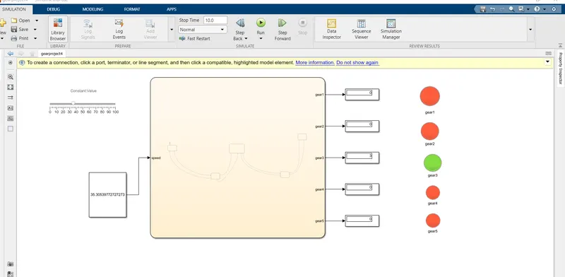
41 to 60 4 th gear
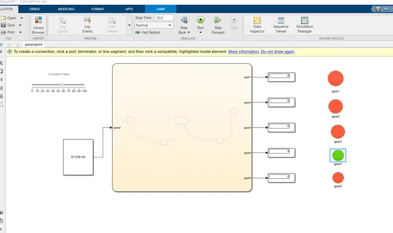
above 61 5th gear
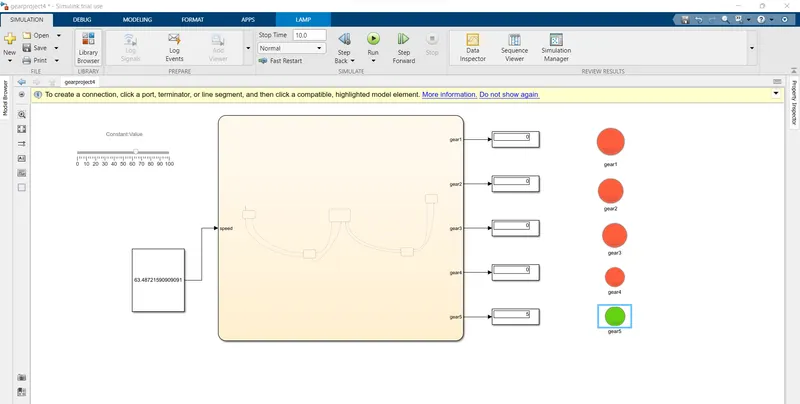
RESULT:
That is how we did the gear shift logic in simulink as we can see the lamp is glow according to the gear it will shows and at the current running accordings to speed we selected from the slider .Output conditions shows system work as per the given condition