Week - 4
aim :
- Implement control logic of a “washing machine” using Stateflow as per given conditions of input power and water supply the lamp will be on and off .
2:conditions :
- If the power supply is available, the system gets activated
- If the Water supply is not available, stop the process & indicate through LED
- Soaking time should be 200s followed by Washing time of 100s.
- Then rinsing happens for next 20s & dryer runs for 50s
After all the processes have completed turn on the finished LED
step : 1 : to create a chart block for defining the stateflow as per given conditions.
2: inside it the circular juntion is create to terminate signals flow of returns .
3: if power is off ie . 0 the process is terminated juntions else the1 c carry forwarded .
4: if power is off ie . 0 the process is terminated juntions else the1 c carry forwarded .
5 : after 300 sec the soaking , the washing block gets activated and washings process is take place.
6 : after 320 sec the washing , the rinsing block gets activated and washings process is take place.
7: after 370 sec the washing , the drying block gets activated and washings process is take place.
8 ; after that signals flow in the procees and exits the chart .
9 : defined the power and water is inputs and soaking washing and drying and rinsing are outputs .
10 :connect the chart inpts and outputs block with slider switch is connected with the constant block with water and power supply and lamp gets connected with all pramters which are takens into outputs cjheck the on of conditions if lamp .
11. the diplay blocks which is connected to show the status of the operating state .
3 : simulink model operating of washing machine as shown as per given conditions .
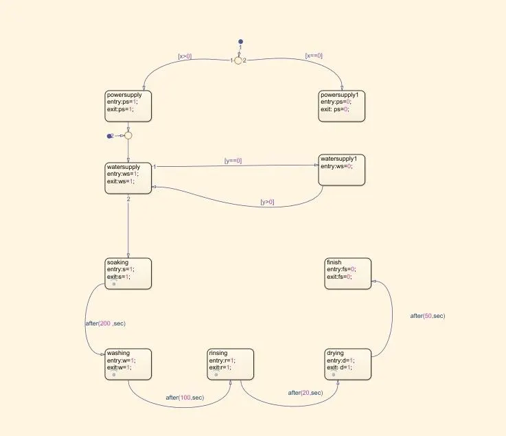
1 : in above logics the juntions is created for 2 conditions when the power supply is available ( x>O ) and power supply is not available ( x == 0) imachine gets activated at entry value 1 will starts for next operation
2 : there are two conditions are made for power supply is on ps =1 and other is power supply is off ps=0
3 ; after power supply we next to select water supply, there are two conditions are made for water supply is on ws =1 and other is power supply is off ws=o
4: fourth operations oif states has been created for soaking after wahing , rinsing and drying the operations of 200 sec for soak, 100 sec for washing and 20 sec for rinse , 50 sec for drying . beacuse of operations of machine .
symbol pane:
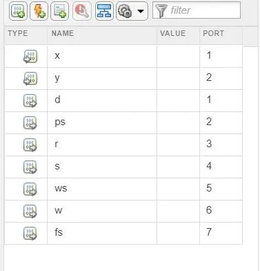
x and y are inpus and outputs are ps ws , r , s , fs ,w, d .
ireespective outputs which are connects to the dispalys which are asssigns and switch which is aslo assign for inputs for on and off operations .
lamp are indications green is for on conditions and red for off .
operatings conditions are givenws belows : 1;water and power supply is on and run time is 370 sec.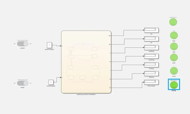
2:power supply iand water supply is off for 370 sec
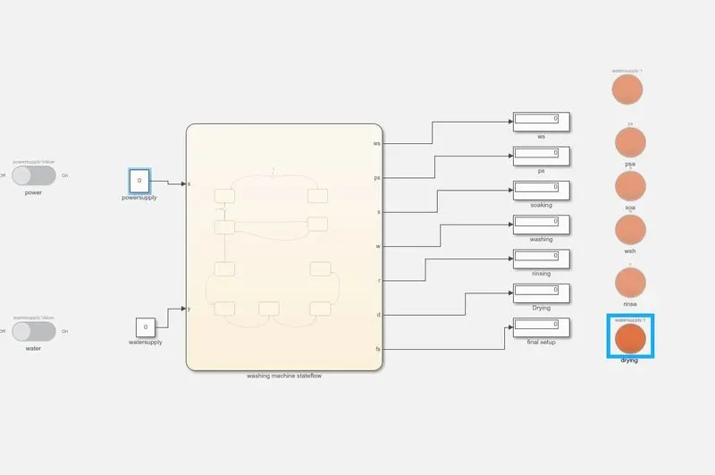
3: ;water and power supply is on and run time is200 sec.( soak state)
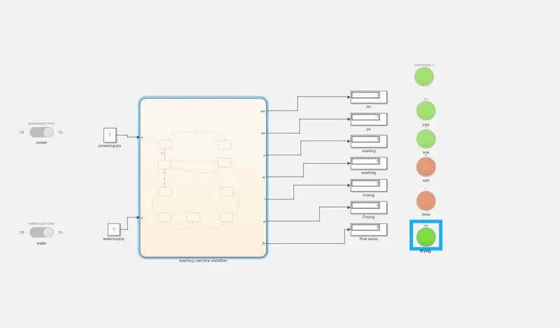
4: ;water and power supply is on and run time is 300sec.( rinse state)
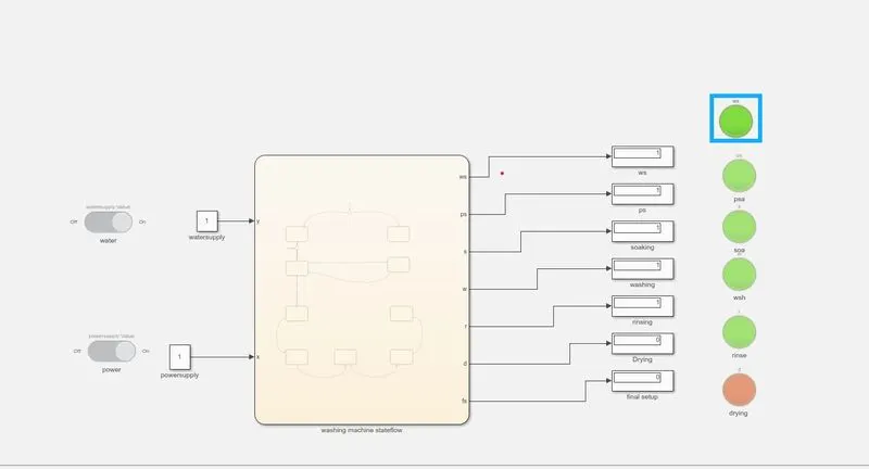
5:water and power supply is on and run time is 320sec.(drying state)
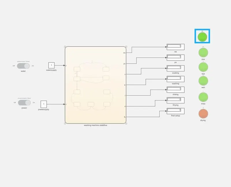
2: aim : Make a Simulink chart for the “Gear shift” logic as per below conditions:Give speed input while the simulation is running & display the gear number.
1 : conditons :
Speed Range(kmph) Gear
0 to 15 1
16 to 25 2
26 to 40 3
41 to 60 4
Above 61 5
steapwise procedure : to create a chart block for defining the stateflow as per given conditions.
1: if speed is less than equal to 0 flow is terminated and gear zero is activated and junctions 1 is carryforwared..
2: if speed is greater than 0 and equal to 15 flow is terminated and gear 1 is activated .
3. if speed is greater than 15and equal to 25 flow is terminated and gear 2 is activated .
4:if speed is greater than 25and equal to 40 flow is terminated and gear 3 is activated .
5: if speed is greater than 40 and equal to 60 flow is terminated and gear 4 is activated .
6:if speed is greater than 60 flow is terminated and gear 5 is activated .
stateflow charts are given conditions :
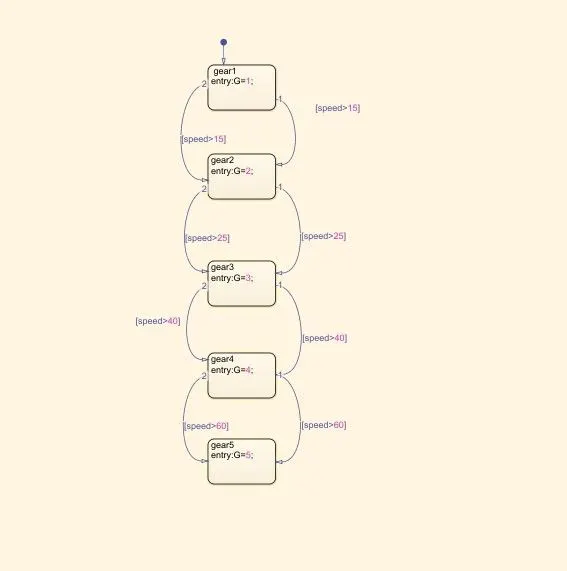
in above stateflow charts shiows conditions of gear is respectively 1,2,3,4, 5etc and default transitions is take from drag menu .
according to speed here we take a transitions .
transitions conditions of gear is decided as
speed >15 shift gear 2 ;l
speed>25 shift to gear 3;
speed >40 shift to gear 4 ;
speed >60 shift to gear 5 . .....speed will increased from (0 to 60)
as per reverse conditions
peed <15 shift gear 2 ;l
speed<25 shift to gear 3;
speed <40 shift to gear 4 ;
speed <60 shift to gear 5 . .....speed will decreased from (0 to 60)
symbol pane :
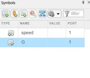
here we take speed is inputs and gear is output .
models:conditions the speed isc less than of 40 andoutputs is gear 3
here we used following block slider gain , constant , display , scope .
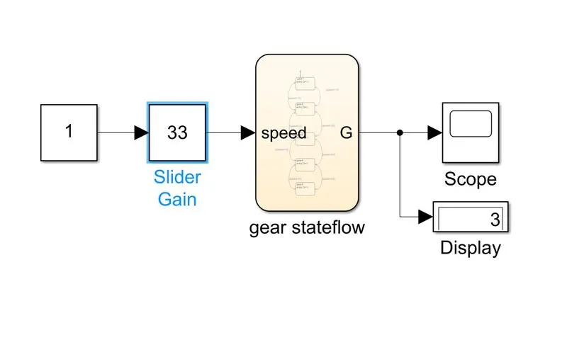
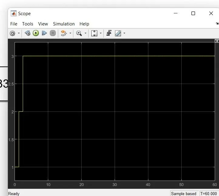
outputs 2 : scope :