Week - 4
Question No.1
Aim:-Implement control logic of a “washing machine” using Stateflow as per given sequence:
- If the power supply is available, the system gets activated
- If the Water supply is not available, stop the process & indicate through LED
- Soaking time should be 200s followed by Washing time of 100s.
- Then rinsing happens for next 20s & dryer runs for 50s.
After all the processes have completed turn on the finished LED.
Apparatus:-MATLAB-Simulink.
Theory:-The washing machine was invented by Jacob Christian Schaffer in 1767 and came as a savior for people specially for women who had to work vigorously to wash all the clothes of their family using their hands.Since its invention, the washing machine has developed a lot, and the recently made automatic ones have taken the manual effort required to almost zero.Like any other electrical appliance, the washing machine operates on some principles governed by physics laws.
Working Principle of Washing machine:-
The main principles behind the working of a washing machine are the centrifugal and centripetal forces, Where centrifugation helps quicken the process of sedimentation of different density particles to clean the laundry in the washing machine.Both the centrifugal and centripetal forces are equal but opposite in direction.
Fig.a.Centripetal & Centrifugal Force.
The washing machine operates in two primary cycles. These are the wash cycle and the rinse cycle.
- The wash cycle involves the principle of centrifugal force. This force’s direction is from inside to outside, which makes sure that every part of the cloth is rinsed adequately in the soap water mixed in the machine.
- The rinse cycle involves the principle of centripetal force. This force acts from outside to inside and creates a vacuum-like space in the middle of the washing machine.
These two cycles work one after another several time, and as a result, the entire cleaning process occurs.
Objective:-
Simulink Model of control logic of a “washing machine”using Stateflow:-
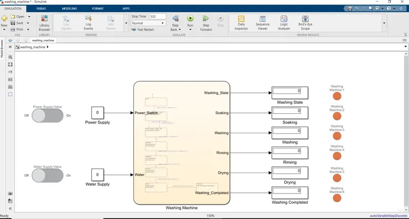
Fig.b. Simulink model of washing machine.
The blocks used in above model are:-
1)Chart:-A finite state machine is a representation of an event-driven (reactive) system. In an event-driven system, the system responds to an event by making a transition from one state (mode) to another. This transition occurs if the condition defining the change is true.
2)Constant:-The Constant block generates a real or complex constant value signal. Use this block to provide a constant signal input.
3)Display:-The Display block shows the value of the input data. You can specify the frequency of the display. For numeric input data, you can also specify the format of the display.
4)Lamp:-The Lamp block displays a color indicating the value of the input signal. You can use the Lamp block with other Dashboard blocks to build an interactivedashboard of controls and indicators for your model. You can specify pairs of input values and colors to provide the information you want during the simulation.
5)Slider Switch:-Set on/off value to tune parameters or variables.
Control logic of a “washing machine”using Stateflow:-
A Slider switch from the dashboard library is used with a constant to supply the power and as water supply. A lamp is used to indicate the power status & water status named as Washing_State in model. The power status is checked at the entry for everystate and the water supply is checked for the soaking and the rinsing process. The timing for each state is as per the given inputs. The status of the running process can be seen by the glowing lamp (red/green) corresponding to the process name.
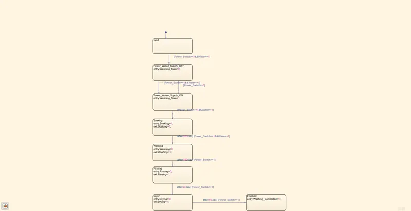
Fig.c. Stateflow control logic of washing machine.
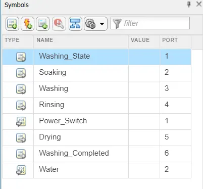
Fig.d.Symbols pane.
- In the above Fig.c. the 1st state is created to get input from supply side i.e. power & water supply named as Input.
- Control logic of following two state is created with 2 conditions for Input .One is with power supply available(Power_Switch==1)and second with water supply available (Water==1).If the power supply at entry is 1 and water supply is on, then machine will get activated and start the next process of operation.
- Following 4 Operation states have been created in flow order Soaking,Washing,Rinsing,Drying with their time of operation as 200sec for a soak,100sec for wash,20sec for rinse & 50sec for dry.Entry and exit condition of the state are kept as 0 & i.e at entry of operation states it is 0 and as operation completes it is 1 for every states.
- After all process has done washing machine completed LED will turned on and we can shut the machine off.
Here, In fig.d. Symbols Pane Power_Switch & Water is as input given while all other like Washing_State, Drying, Washing, Soaking, Rinsing, Washing_Completed are all output given.
Process:
1.Start simulink and create a blank model.
2.Search for chart block in the stateflow category of library browser.
3.Open the chart block and select the state feature from the stateflow window.
4.Control logic for washing m/c is such that it should soak the water for the first 200sec followed by washing time of 100sec. Rinsing the water for the next 20sec followed by drying time of 50sec.
5.After finishing the control logic run the STATEFLOW and check the sequence of operation for 370sec
Observation:-
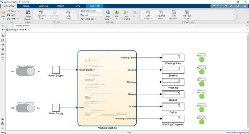
Fig.e.Complete Simulink Model, Showing that the washing process is completed.
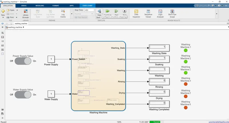
Fig.f.Simulink Model, Showing that the washing process is completed & Rinsing is going on.
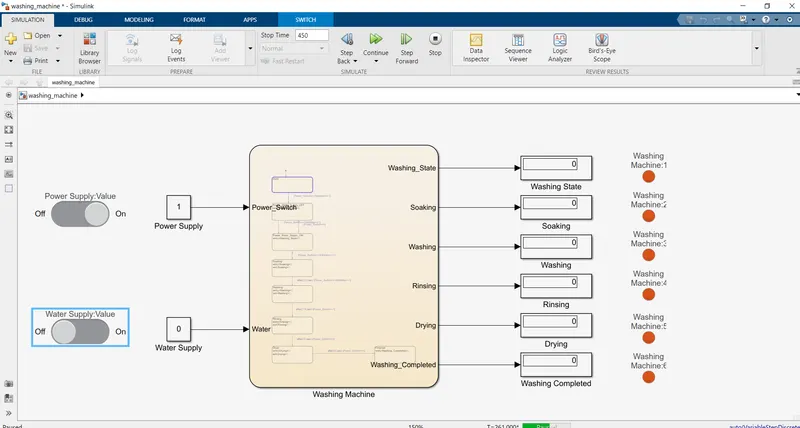
Fig.g. Simulink Model, showing as water supply is off/stop then washing process stop.
Here Red light means operation is not completed and green light shows operation is completed which is also check from display box as output 0 &1 respectively
Result:-The control logic of a “washing machine” using Stateflow as per given sequence has been created & simulated successfully.
Question No.2
Aim:-Make a Simulink chart for the “Gear shift” logic as per below conditions:
Speed Range(kmph) Gear
0 to 15 1
16 to 25 2
26 to 40 3
41 to 60 4
Above 61 5
Give speed input while the simulation is running & display the gear number.
Apparatus:-MATLAB-Simulink.
Theory:- Vehicle Transmission system.
A vehicle's transmission system is a complex and integral part of the way the vehicle runs. In fact, it’s probably the most complex system in the vehicle.
1)Transmission:- It is the part of the vehicle that connects to the back of the engine offering power from the engine to the wheels. The transmission uses the power created in the engine to keep the wheels spinning and keep the engine within a certain revolutions per minute range. Each vehicle is different in the range required, so the transmission needs to be tuned to your vehicle. The arrangement of the transmission and where it sits is dependent on whether the car is all-wheel drive, front-wheel drive, or rear-wheel drive.
2)Planetary Gear sets:-This gears work together to keep the proper RPM ratio and connect to the input shaft. The reason the system is called a planetary gear set is because it uses a central gear as a sun and two or more smaller gears as a planet. These are held together with an outer ring. While the central gear stays in the same place, the smaller gears are working around it, like planets in a solar system.
3)Hydraulic system:-In the transmission, there is a hydraulic system that helps control the shifting of gears, lubricates parts for optimal performance, and keeps the entire transmission system cool. The hydraulic system is used to help manipulate the fluid within the transmission to create pressure and keep the vehicle going. The hydraulic system is an integral part of the oil pump, clutches, bands, and more to keep the transmission in good repair and well-lubricated. If we’ve ever had to add transmission fluid to our vehicle, it’s good to know that this fluid goes straight into the hydraulic system.
4)Torque converter:-If we're driving an automatic transmission car, the torque converter takes the place of a clutch. This system allows the vehicle to keep running, even when you’re stopped. The torque converter mounts between the transmission itself and the engine. While it is not inside the transmission, it is an important part of your transmission system. Using a turbine, pump, and stator, the torque converter helps keep your engine speed consistent in the optimal range. These pieces work together within the converter housing to provide power and direct the flow of oil.
Objective:-
Simulink Model of “Gear shift” logic Using Stateflow.
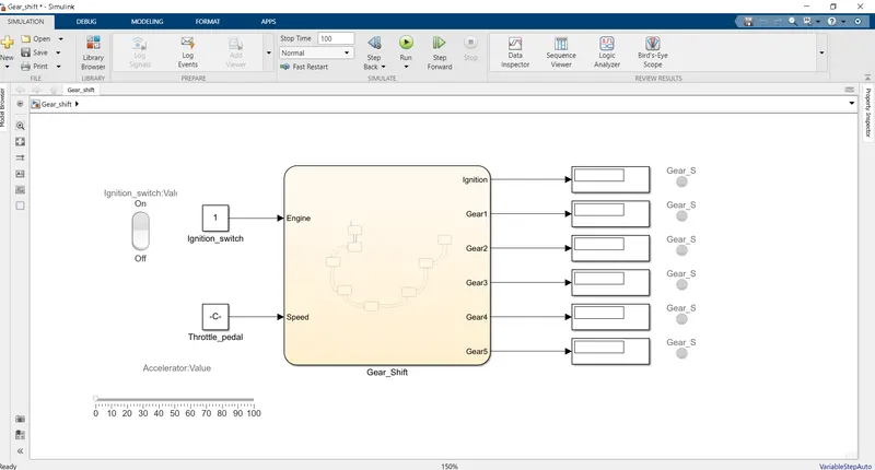
Fig.a.Simulink Model of a “Gear shift”.
The blocks used in above model are:-
1)Chart:-A finite state machine is a representation of an event-driven (reactive) system. In an event-driven system, the system responds to an event by making a transition from one state (mode) to another. This transition occurs if the condition defining the change is true.
2)Constant:-The Constant block generates a real or complex constant value signal. Use this block to provide a constant signal input.
3)Display:-The Display block shows the value of the input data. You can specify the frequency of the display. For numeric input data, you can also specify the format of the display.
4)Lamp:-The Lamp block displays a color indicating the value of the input signal. You can use the Lamp block with other Dashboard blocks to build an interactivedashboard of controls and indicators for your model. You can specify pairs of input values and colors to provide the information you want during the simulation.
5)Rocker Switch:-The Rocker Switch block toggles the value of the connected block parameter between two values during simulation. For example, you can connect the Rocker Switch block to a Switch block in your model and change its state during simulation.
6)Slider:-The Slider block tunes the value of the connected block parameter during the simulation. For example, you can connect the Slider block to a Gain block in yourmodel and adjust its value during the simulation. You can modify the range of the Slider block's scale to fit your data. Use the Slider block with other Dashboardblocks to create an interactive dashboard to control your model.
Control logic of a “Gear shift”using Chart:-
The speed ranges from 0 to 100 and the slider is used to send the input. The 1st gear has speed values from 0 to 15 so the entry condition for the 1st gear is 0<=speed and speed<=15 and the exit condition is when the speed greater than 15.Similarly for 2nd gear, the entry condition is 16<=speed and speed<=25 the exit condition is when speed<16 and speed>25. In the same way for each gear, the entry and the exit condition are specified and the out is mapped to the lamp and the display block.
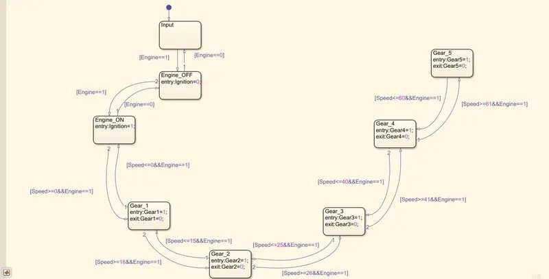
Fig.b. Chart of control logic of Gear shift.
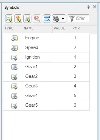
Fig.c. Symbol pane.
- In the above Fig.b. control logic , the 1st state is created to get input from supply side i.e.Engine & Speed.
- Then from following state Engine is started from input switch Ignition_Switch=0/1 through Rocker switch which is power switch to make engine ON.Then next Gear_Shift_logic implemented through following states.
- Five Gear State is created with state condition of gear Gear_1,Gear_2,Gear_3,Gear_4and Gear_5 respectively and their transition is connected with speed range condition as shown.
- The transitions condition for the gear shift is decided as
Speed>15 shift to Gear2
Speed>25 shift to Gear3
Speed >40 shift to Gear4
Speed>60 shift to Gear5 when the speed is increasing from 0-60 kmph
Similarly in reverse direction
Speed<60 shift to Gear4
Speed<40 shift to Gear3
Speed<25 shift to Gear2
Speed<15 shift to Gear1 when the speed is decreasing from 60-0 Kmph
- While simulating Gear_Shift_logic , Engine [Engine==1] condition given with various speed change values.
Observations:-
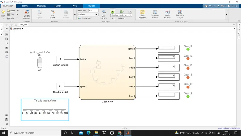
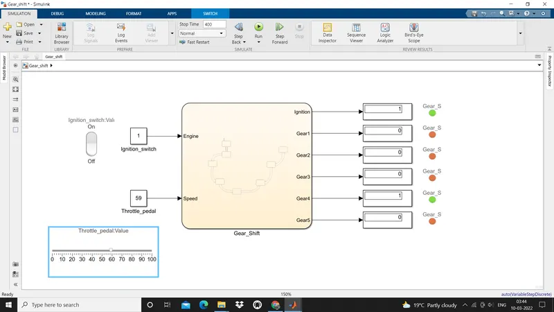
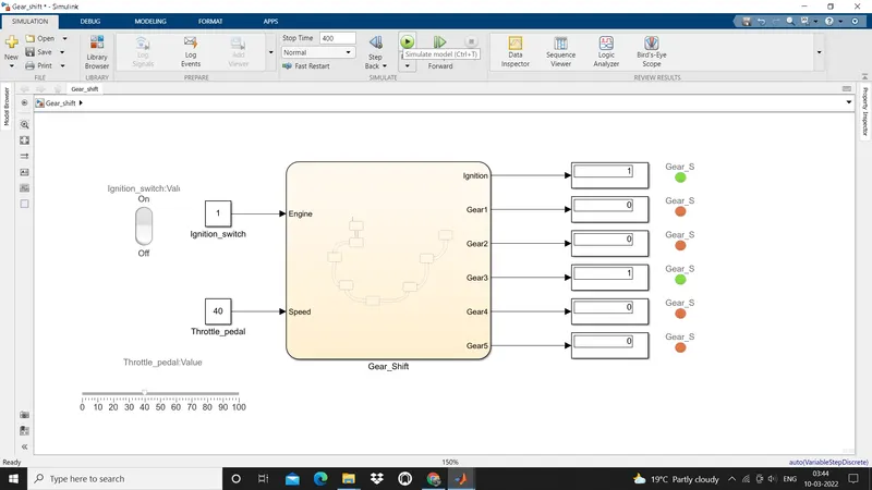
Simulink Output at different speed.
1)At speed 71kmph.
2)At speed 59kmph.
3)At speed 40kmph.
4)At speed 24kmph.
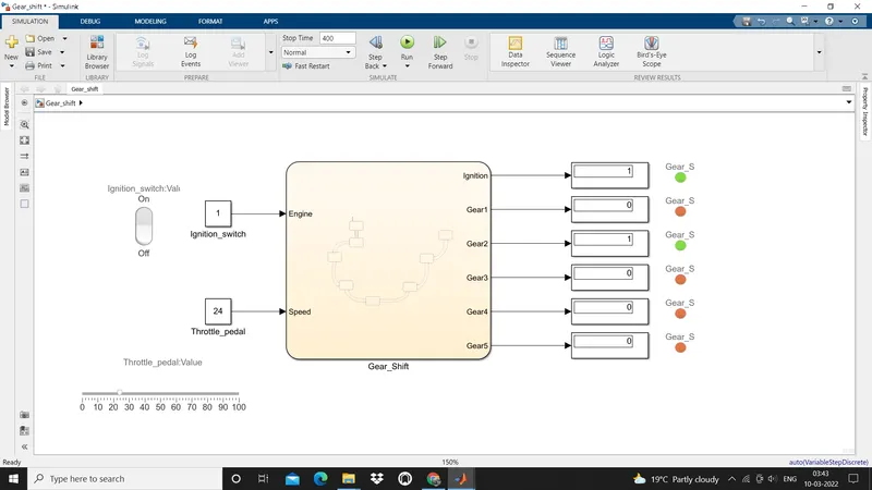
5)At speed 15 kmph.
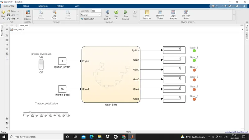
Result:-The control logic of a “Gear Shift” using chart as per given sequence has been created & simulated successfully.