Project
Aim:-To carry out a system-level simulation of an all-terrain vehicle(ATV) using Simulink & prepare a technical report explaining the model properties & comments on the results.
Objective:-To study "BAJA all-terrain vehicle(ATV)" model, explaining the properties & various result obtain from following:-
1.Without using Lookup table.
- without dashboard.
- with dashboard.
2.Using Lookup table.
- Lookup Table data extraction.
- Mapped Lookup Table Without Dashboard.
- Mapped Lookup Table With Dashboard.
Theory:-
a)BAJA-SAE:-Baja SAE is an Collegiate Design Series competition run by the Society of Automotive Engineers International (SAE International). Teams of students from universities all over the world design and build small off-road vehicle. The vehicle all have engines of the same specifications.The goal in Baja SAE racing is to design, build and race off-road vehicles that can withstand the harshest elements of rough terrain. The vehicles used in Baja SAE racing are often similar in appearance to dune buggies. Before 2007, the events were called "Mini Baja."
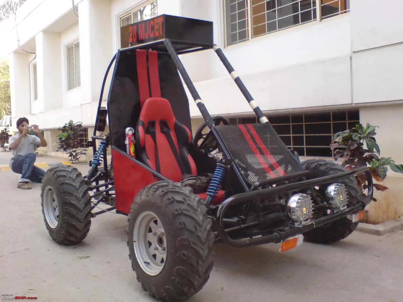
Fig.a BAJA-car.
All cars must adhere to SAE International's rules, and pass SAE's technical inspection and judging; a car may not race until all safety inspections are passed. Small engine manufacturer Briggs & stratton sponsors Baja SAE teams by providing the SAE sanctioned engine free of charge, at a replacement rate of one engine for every two years in competition.
b)ATV:-An all-terrain vehicle (ATV) is defined as a vehicle with a straddle seating position, handlebar steering, and the ability to maneuver through a variety of terrain conditions.While there are a variety of ATV customizations and modifications available, at their base all ATVs share those three features.Some other specification of an ATVs are:-
- Wheels & tires:-ATVs have either three or four wheels. Tires are kept at a lower pressure than standard car or UTV (Utility Terrain Vehicle) tires.In general it is called as a four-wheeler or quad bike.
- Steering:-The operator can steer the ATV by using handlebars.
- Seating & passenger capacity:-On an ATV, the operator is seated in a straddle position. ATVs are normally built for just one rider, some are made to carry the operator and one passenger.
- Speed & handling:-ATVs are not “one-size-fits-all” and should be sized appropriately for the operator.When operated safely and correctly, ATVs offer a quick and nimble means of transportation over a variety of terrain.
- Breaking & acceleration:-The majority of stock ATVs come with a thumb throttle. Pressing the throttle with the thumb controls acceleration. It is possible to modify an ATV to use a twist throttle, which allows the operator to control the vehicle’s acceleration by twisting the ATV’s handle.To brake, operators can use either the brake handle or the foot pedal, depending on what type of ATV they are operating.
- Safety equipment:-ATVs often do not come with safety equipment as part of the vehicle. Some do have “roll bars”—strong steel pipes that form a cage-like structure around the operator to provide protection if the vehicle rolls.ATV operators should strongly consider wearing protective clothing, boots, and gloves—and should always wear a helmet.
- Cabin:-ATVs are open and do not have a cabin. However, as mentioned above, some do have roll bars.
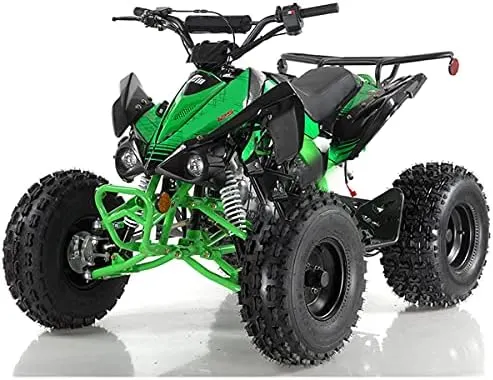
Fig.b Image of an ATV (Quad bike).
- Uses:-As a quick means of transportation over rough ground, ATVs are a valuable tool. However, they are mainly used for recreation, like racing or trail riding.They’re frequently used in agriculture and forestry since they’re good for accessing hard-to-reach areas and navigating difficult terrain. You’ll also find them used by search and rescue operators, law enforcement in remote areas, surveyors and oil and gas industry professionals.ATVs are also popular powersports vehicles. Racing ATVs is an exciting hobby, and ATV trail riding is great for those who want to enjoy nature and powersports at the same time. Many popular tourist destinations now offer ATV tours that take riders on exciting trips through the local landscape.
c)Continuously Variable Transmission(CVT):-The term CVT stands for continuously variable transmission.In general, there are three different types of transmissions. Even if we don't know much about how a transmission works, we have probably heard of the manual and the automatic. The CVT is the newest type of transmission. It is sometimes referred to as the shiftless transmission and is a type of automatic.
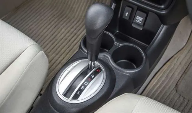
Fig.c CVT Gearbox.
CVT working:-In order to see how a CVT works,we need to understand a manual and a traditional automatic. A manual has a set number of gears, and the driver determines what gear ratio they need. An automatic also has a set number of gears, but it uses a hydraulic system that responds to pressure created by the conditions to determine the gear needed without any input from the driver.
A CVT is similar to an automatic in that it doesn't use any input from the driver, but that is where the similarities end. A CVT doesn't have any gears. Instead, it has two pulleys. One pulley connects to the engine, and the other connects to the wheels. A flexible belt connects the two pulleys.The width of the pulleys changes depending on how much power the vehicle needs. When one pulley gets larger, the other one gets smaller. Since neither the pulleys or the belt are fixed, they can provide an infinite number of gear ratios, unlike the automatic, which has a set number of gears.
Not all CVTs are created the same. The most common type is the pulley-based, but some other types include the Toroidal CVT, which uses rotating discs along with power rollers to produce the same result as the pulleys. The hydrostatic CVT uses pumps to control fluid flow, which then produces a rotational motion.
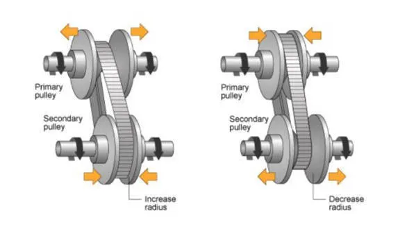
Fig.d Pulley based CVT.
Advantages:-
- Fuel economy is significantly improved. Modern hybrids make use of CVTs for gasoline (petrol/diesel) efficiency.
- Driving uphill is less difficult with a CVT in accordance to Certified Transmission Repair. A regular transmission has to paintings tougher to locate the proper tools ratio for the drive, while a CVT reveals the precise ratio wished almost immediately, permitting the engine to seamlessly offer energy without difficult shifting.
- Because there are not any difficult gear shifts, CVTs additionally can help you experience clean riding and acceleration at any pace.
Disadvantages:-
- CVT systems are typically greater expensive than traditional counterparts.
- CVTs can be expensive to repair or replace when compared to a conventional automatic transmission.
- Since CVTs depend on the belts to operate, if these suffer from excessive stretching or too much wear, the transmission can completely fail.They can fail round 100,000 miles, even as a traditional transmission can last as long as two times that.
- Some of the common problems that driver(people) run into include overheating, slipping, and sudden loss of acceleration. Shuddering is also a common problem.
- Continuously variable transmissions cannot cope with the improved horsepower, that is why they are not used on sports activities coupes and overall performance cars.
- The general public has been less accepting of the CVT due to the difference in noise perception from mechanical or step automatic transmission.Drivers tend to make a complaint about a CVT is the loud droning sound that occurs during acceleration. This happens because the CVT forces the engine to continuously run a constantly high rpm as it gets up to speed.
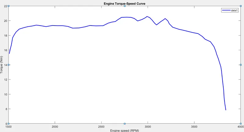
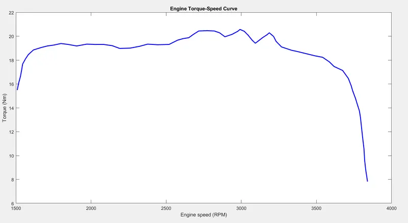
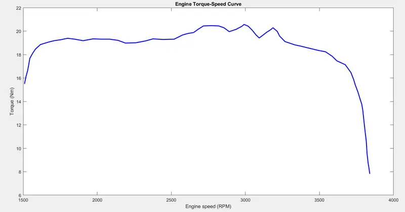
BAJA ALL-Terrain Vehicle (ATV) Model:-This submission contains a set of models created with Simulink, Simscape, and Simscape Driveline.More specifically, the file contained includes BAJA ATV model with Continuously Variable Transmission(CVT).These models show how to build an ATV with CVT which is mostly used in BAJA competitions. Simscape and Simscape Driveline have been used to complete the system. The engine data used in the model is provided as an image which shows the Engine Speed (RPM) Vs Torque curve.
Objective1:- BAJA ATV Model Without using Lookup Table:-
a)Without Dashboard:-
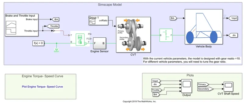
Fig.e Simulink Model of BAJA ATV Without dashboard.
Common blocks used in above model(Fig.e.) are:-
1)Signal Builder:- The Signal Builder block allows you to create interchangeable groups of piecewise linear signal sources and use them in a model. You can quickly switch the signal groups into and out of a model to facilitate testing.
2)Generic Engine:-The Generic Engine block represents a general internal combustion engine. This block is a suitable generic engine for spark-ignition and diesel. Speed-power and speed-torque parameterizations are provided. A throttle physical signal input specifies the normalized engine torque. Optional dynamic parameters include crankshaft inertia and response time lag. A physical signal port outputs the engine fuel consumption rate based on the fuel consumption model that you choose. Optional speed and redline controllers prevent engine stall and enable cruise control.
3)Engine sensor:-Engine sensor is a subsystem consisting of following blocks shown in Fig.f.
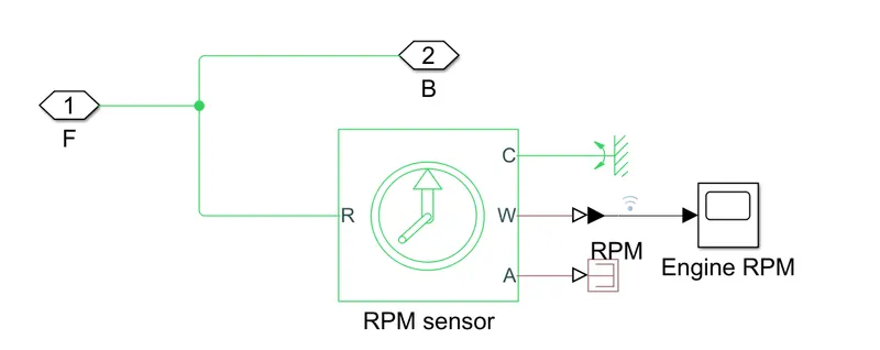
Fig.f Engine sensor.
a)Ideal Rotational Motion Sensor:-The Ideal Rotational Motion Sensor block represents an ideal mechanical rotational motion sensor, that is, a device that converts an across variable measured between two mechanical rotational nodes into a control signal proportional to angular velocity or angle. You can specify the initial angular position (offset) as a block parameter.
The sensor is ideal since it does not account for inertia, friction, delays, energy consumption, and so on.Connections R and C are mechanical rotational conserving ports that connect the block to the nodes whose motion is being monitored. Connections W and A are physical signal output ports for velocity and angular displacement, respectively.
b)Mechanical Rotational Reference:- The Mechanical Rotational Reference block represents a reference point, or frame, for all mechanical rotational ports. All rotational ports that are rigidly clamped to the frame (ground) must be connected to a Mechanical Rotational Reference block.
c)PS Terminator block:-Use the PS Terminator block to cap physical signal output ports that do not connect to other blocks.Unlike conserving ports in physical modeling, or Simulink output ports, unconnected physical signal output ports do not generate warnings. However, you can use a PS Terminator block for clarity, to indicate that the signal was not inadvertently left unconnected.
d)Scope:-Display signals generated during simulation.

4)Simple Gear:-Represents a fixed-ratio gear or gear box. No inertia or compliance is modeled in this block. You can optionally include gear meshing and viscous bearing losses.The Simple Gear block represents a gearbox that constrains the connected driveline axes of the base gear, B, and the follower gear, F, to corotate with a fixed ratio that you specify. You choose whether the follower axis rotates in the same or opposite direction as the base axis. If they rotate in the same direction, the angular velocity of the follower, ωF, and the angular velocity of the base, ωB, have the same sign. If they rotate in opposite directions, ωF and ωB have opposite signs. You can easily add and remove backlash, faults, and thermal effects.
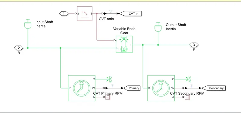
5)CVT :-CVT is a subsystem consisting of following blocks shown in Fig.g.
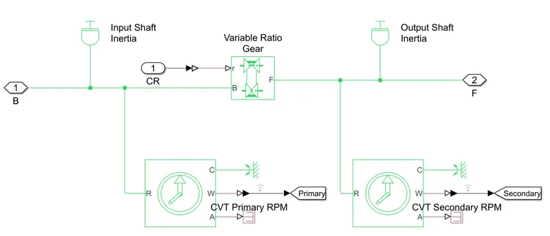
Fig.g CVT.
a)Inertia:-
The block represents an ideal mechanical rotational inertia.The block has one or two mechanical rotational conserving ports. The difference is purely graphical, as the ports are rigidly linked. The block positive direction is from its port to the reference point. This means that the inertia torque is positive if the inertia is accelerated in the positive direction.
b)Variable Ratio Transmission:-Represents a variable ratio gearbox such as implemented by mechanical belt CVT, electric, or hydraulic transmissions. The physical signal input r defines the ratio of input to output angular shaft velocities.Connections B (base) and F (follower) are mechanical rotational conserving ports. Specify the relation between base and follower rotation directions with the Output shaft rotates parameter.
c)Ideal Rotational Motion Sensor.
d)Mechanical Rotational Reference.
e)PS Terminator block.
6)Vehicle Body:-Vehicle body is a subsystem consisting of following blocks shown in Fig.h.
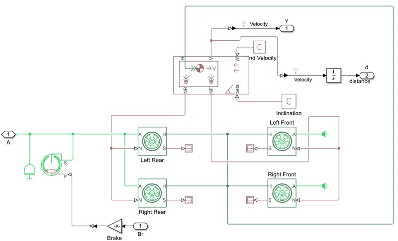
Fig.h Vehicle body.
a)Vehicle body:-The Vehicle Body block represents a two-axle vehicle body in longitudinal motion. The vehicle can have the same or a different number of wheels on each axle. For example, two wheels on the front axle and one wheel on the rear axle. The vehicle wheels are assumed identical in size. The vehicle can also have a center of gravity (CG) that is at or below the plane of travel.
The block accounts for body mass, aerodynamic drag, road incline, and weight distribution between axles due to acceleration and road profile. Optionally include pitch and suspension dynamics. The vehicle does not move vertically relative to the ground.
The block has an option to include an externally-defined mass and an externally-defined inertia. The mass, inertia, and center of gravity of the vehicle body can vary over the course of simulation in response to system changes.
b)Tire(Magic Formula):-Represents the longitudinal behavior of a highway tire characterized by the tire Magic Formula. The block is built from Tire-Road Interaction (Magic Formula) and Simscape Foundation Library Wheel and Axle blocks. Optionally, the effects of tire inertia, stiffness, and damping can be included.
Connection A is the mechanical rotational conserving port for the wheel axle. Connection H is the mechanical translational conserving port for the wheel hub through which the thrust developed by the tire is applied to the vehicle. Connection N is a physical signal input port that applies the normal force acting on the tire. The force is considered positive if it acts downwards. Connection S is a physical signal output port that reports the tire slip. Optionally expose physical signal port M by setting Parameterize by to Physical signal Magic Formula coefficients. Physical signal port M accepts a four element vector corresponding to the B, C, D, and E Magic Formula coefficients.
c)Double-shoe Brake:-Represents a brake arranged as two pivoted rigid shoes symmetrically installed inside or outside a drum and operated by one actuator. The actuator force causes the shoes to exert a friction torque on a shaft connected to the drum.Connection S is a conserving rotational terminal associated with the drum shaft. Connection F is a physical signal port representing the force input to the actuator. Positive force creates friction torque that resists shaft rotation. Optionally include thermal effects and expose thermal conserving port H by setting Thermal port to Model.
d)Integrator:-Continuous-time integration of the input signal.The Integrator block outputs the value of the integral of its input signal with respect to time.

e)PS Constant:-The PS Constant block generates a physical signal of a constant value. You specify the value and unit of the signal as the Constant parameter.
f)PS Gain:-The PS Gain block performs element-wise multiplication of the input physical signal by a constant value (gain). You specify the gain as the Gain parameter value and unit.The input signal value is multiplied by the value of the Gain parameter.
g)Rotational free end:-This block represents a mechanical rotational free end. Use it to allow a node to rotate freely without torque. Rotational port terminator with zero torque.This block can be used to optionally specify initial rotational velocity.
h)Inertia.
i)PS Terminator block.
j)Simulink-PS converter:-The Simulink-PS Converter block converts the input Simulink® signal into a physical signal. Use this block to connect Simulink sources or other Simulink blocks to the inputs of a Simscape™ physical network.
k)PS-Simulink Converter:-The PS-Simulink Converter block converts a physical signal into a Simulink® output signal. Use this block to connect outputs of a Simscape™ physical network to Simulink scopes or other Simulink blocks.
7)Mechanical rotational reference:-This block represents a mechanical rotational reference point, that is, a frame or a ground. Use it to connect mechanical rotational ports that are rigidly affixed to the frame (ground).
8)Solver Configuration:-Each physical network represented by a connected Simscape™ block diagram requires solver settings information for simulation. The Solver Configuration block specifies the solver parameters that your model needs before you can begin simulation.Each topologically distinct Simscape block diagram requires exactly one Solver Configuration block to be connected to it.
Working procedure:-
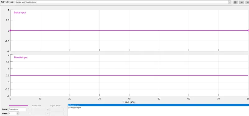
- The throttle signal is generated by signal builder block & proceeded to generic engine block.
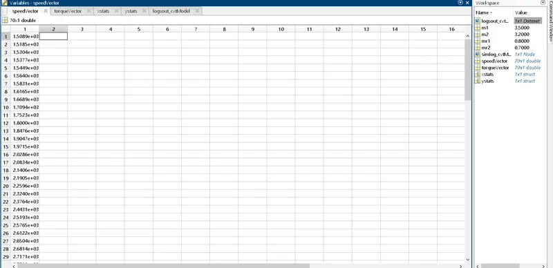
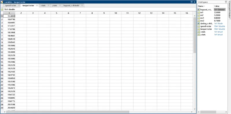
- The torque & speed vector input given to generic engine block which are stored in MATLAB workspace.
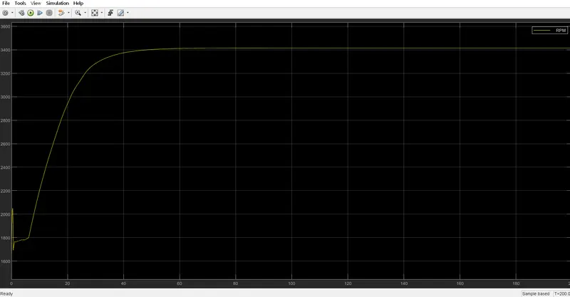
- The engine will generate the output rotation(rpm) which can be taken from crankshaft output.This speed will given to the Ideal rotational motion sensor to sense the output speed(rpm).
- The same output speed will be given to simple gear mechanism to reduce the speed where gear ratio is 10.
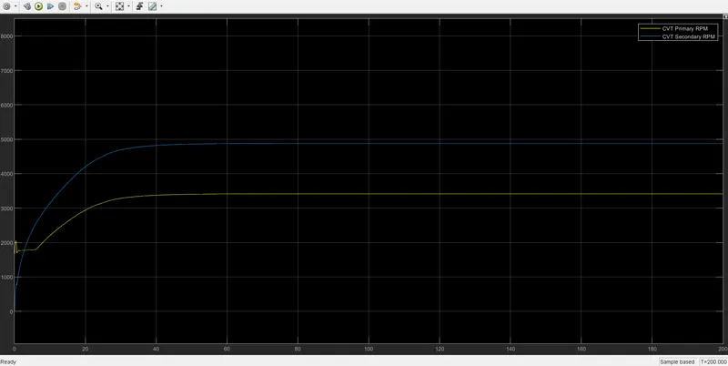
- Then the output speed from gear reducer will be given to the Variable Ratio Transmission Block(CVT).
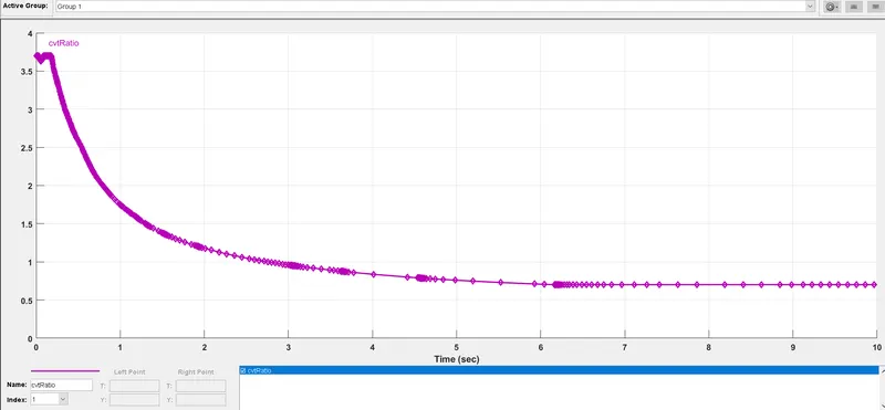
- The CVt ratio is provided to the Variable Ratio Transmission (CVT) block through Signal Builder Block.
- The speed is controlled by the variable CVT ratios & the controlled output speed given to the vehicle axle.
- The brake signal is given to vehicle body (Double shoe brake) for applying brake to the axle.
- The power from CVT is given to axle & vehicle accelerates according to the speed.
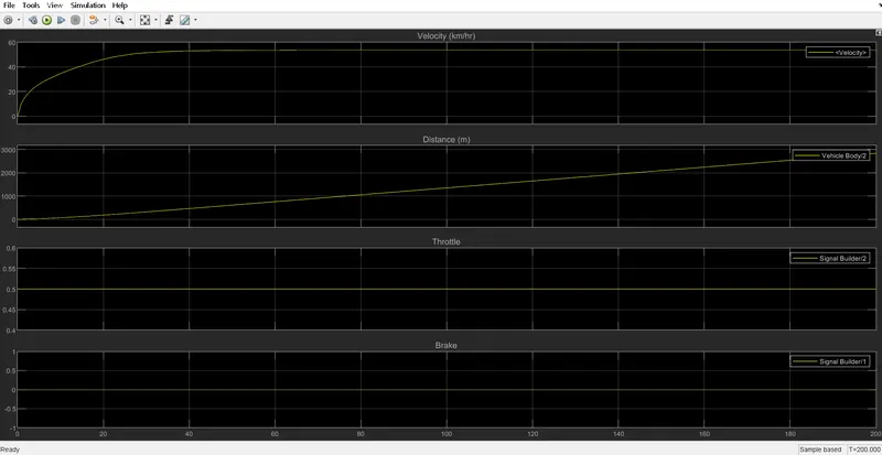
- Then the velocity is taken as output from vehicle body for further analysis.
Obsevations:-
1)Brake & Throttle input:-
2)CVT Ratio:-
3)Engine Torque Speed Characterstic Curve:-
a)Speed Vector Variable:-
b)Torque Vector Variable:-
4)Engine Speed:-
5)CVT Shaft Speed:-
6)Output:-
b)With Dashboard:-The Simulink model of BAJA ATV with dashboard & without dashboard are same, the only difference is that break & throttle input are controlled by user by using input knob on dashboard & with signal builder block in without dashboard model.
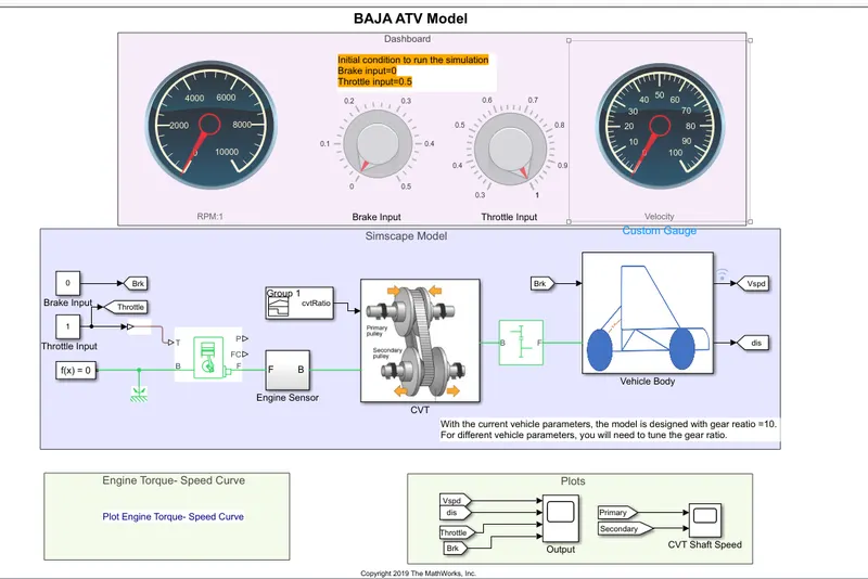
Fig.i.Simulink Model of BAJA ATV With dashboard.
a)Dashboard:-Blocks that can control parameter values and display signal values during simulation.We can use dashboard blocks to build an intuitive and interactive interface for your model. The control blocks, such as the Knob block, connect to variables or tunable parameters in our model and allow us to interactively modify the value of the connected element during simulation. The display blocks connect to signals in the model and display the signal value during simulation. For more information, see Control Simulation With interactive display.
WE can design dashboard blocks that look like controls and displays in our real system using the blocks in the Customizable Blocks library.In this model(Fig.i) it is comprises of brake & throttle input through a knob which can be varied manually through user unlike through signal builder in previous case.The Engine RPM guage & velocity guage displays the changes done by the respective knob.The initial Position/conditions of knobs used for Brake input & Throttle input in above(Fig.i) dashboard are 0 & 0.5 respectively.
Working procedure:-The model workflow process is same as the process of "BAJA ATV model without dashboard" but the throttle & brake input are controlled by user with the knob from dashboard.
Observations:-
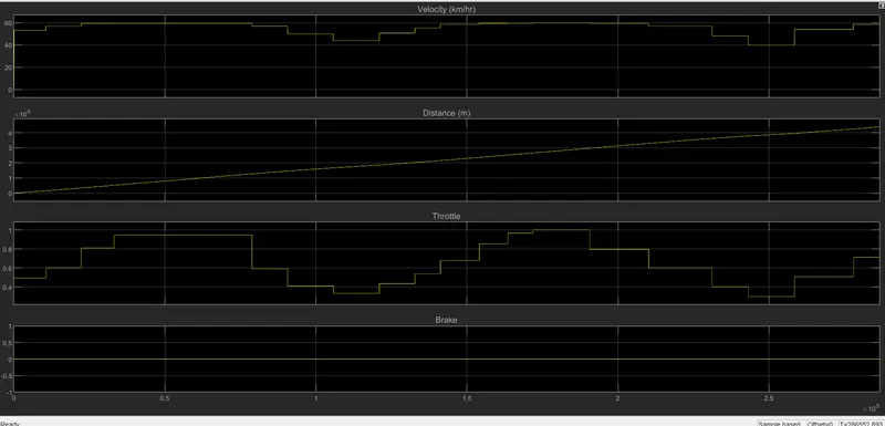
1)Output:-
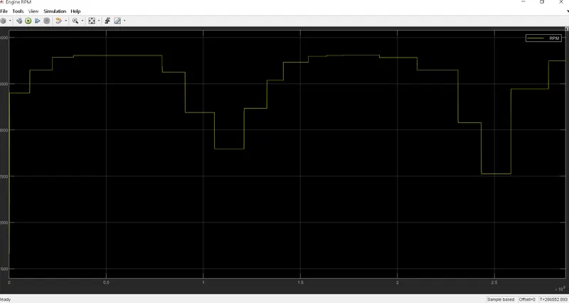
2)Engine Speed:-
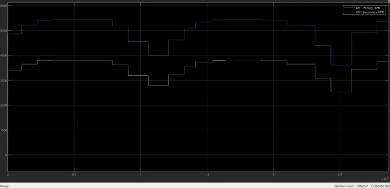
3)CVT Shaft Speed:-
4))Engine Torque Speed Characterstic Curve:-
Objective2:-BAJA ATV Model by using Lookup Table.
a)BAJA ATV Model by using Lookup Table Data Extraction.
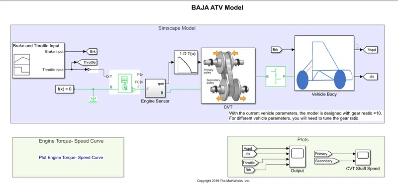
Fig.j Simulink model of BAJA ATV with Lookup Table Data Extraction.
The blocks used in above model(Fig.j) are almost same as previous 2 model,the only difference is that here we used 1-D Lookup table input to CVT ,where data is extracted from workspace of a model.
1)1-D Lookup Table:-Perform n-dimensional interpolated table lookup including index searches. The table is a sampled representation of a function in N variables. Breakpoint sets relate the input values to positions in the table. The first dimension corresponds to the top (or left) input port.

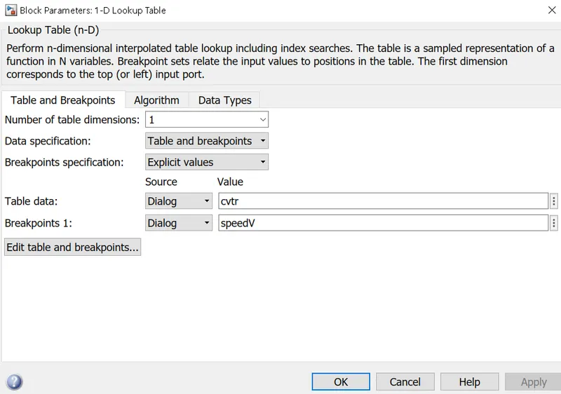
Fig.k. 1-D Lookup Table input parameter.
Working Procedure:-The workflow process of "BAJA ATV Model by using Lookup Table data extraction" is same as previous two cases/models.The small addition is here that CVT Ratio and vehicle speed data are extracted from Workspace.
Observations:-
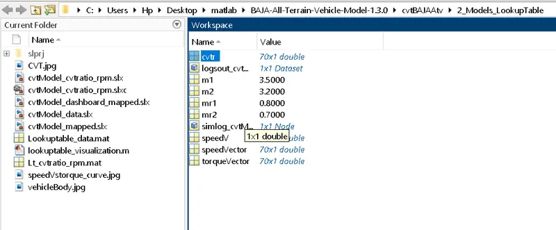
a)Workspace Data Before Simulation:-
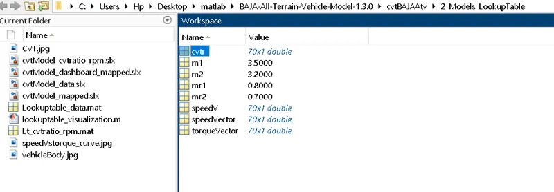
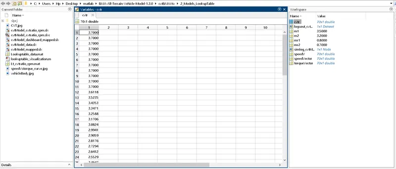
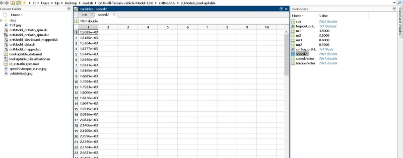
b)Workspace Data after Simulation:-
1)
2)CVT Ratio(cvtr) Data:-
3)Vehicle speed(Speedv) Data:-
Remaining Results of this system model is as same as "BAJA ATV MOdel without using Lookup Table & Dashboard Model " (Fig.e).
b)BAJA ATV Model -Mapped Lookup Table Without Dashboard:-
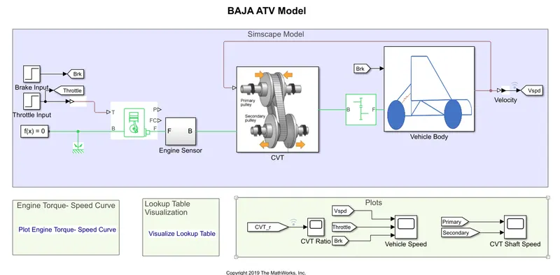
Fig.l BAJA ATV Model -Mapped Lookup Table Without Dashboard.
The Simulink Model of "BAJA ATV Model -Mapped Lookup Table Without Dashboard" comprises of a Throttle & Brake input of a step block which is used for step output & for CVT ratio Lookup Table is used.
1)Step:-It generate step function.The Step block provides a step between two definable levels at a specified time. If the simulation time is less than the step time parameter value, the block's output is the Initial value parameter value. For simulation time greater than or equal to the Step time, the output is the Final Value parameter value.

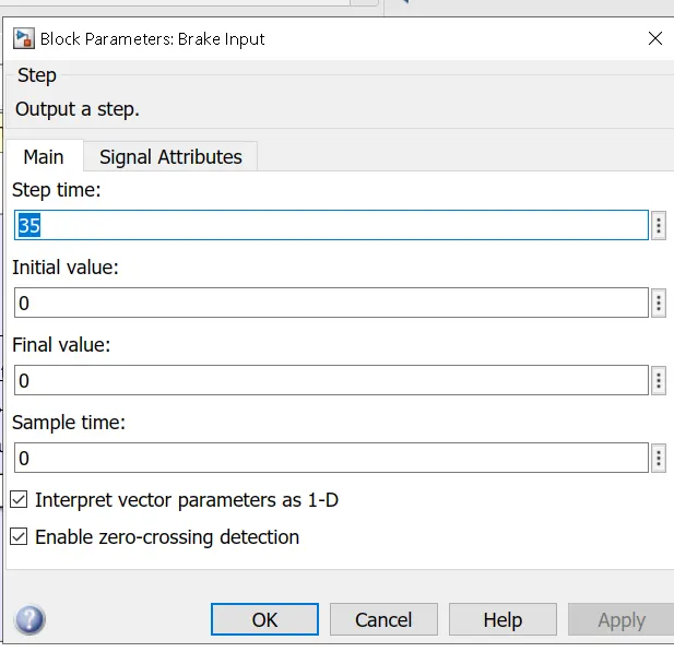
Fig.m Input parameter of Brake Input.
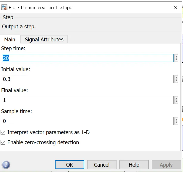
Fig.n Input parameter of Throttle Input.
2)CVT Model:-
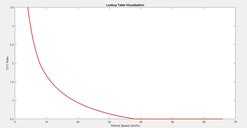
PS-Lookup Table(1D):-This block represents a physical signal converter whose input-output relationship is specified by a lookup table. The table grid must be in strictly ascending or strictly descending order, but the spacing can be nonuniform.Right-click on the block and select Foundation Library > Plot Table to visualize the table data based on the selected interpolation and extrapolation methods.
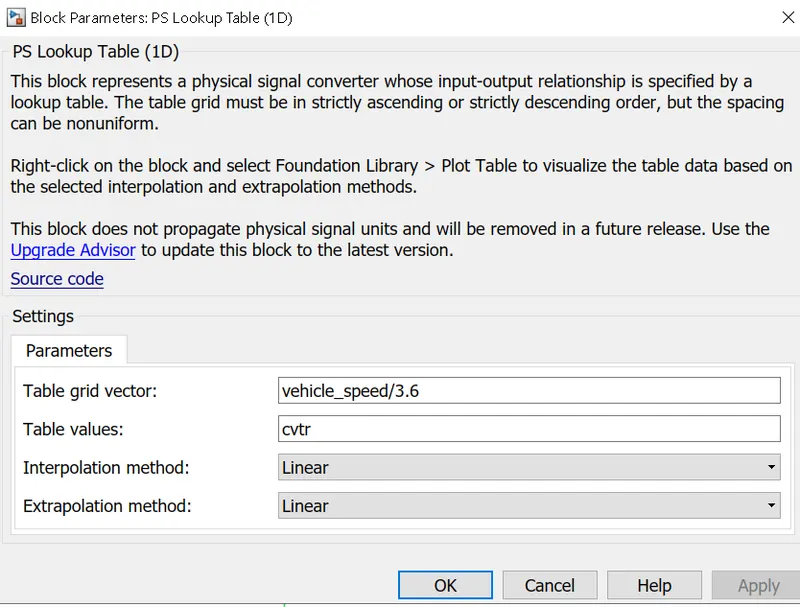
Fig.o CVT Ratio input parameter.
Working procedure:-
- The workflow process of current system is as same as "BAJA ATV model without Lookup table & dashboard" (Fig.e).
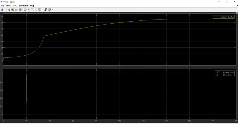
- Instead of signal builder blocks for Brake & throttle input , we employed step block here. At 35 sect he Brake input will Take step value '0' & at 20 sec throttle input will increase from 0.3 to 1 then remain constant throughout.
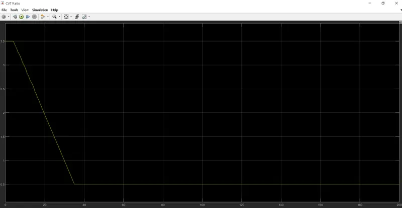
- Instead of signal builder block for CVT ratio the PS Lookup table(1D) is used.The intrapolation & extrapolation method are set linear for that.
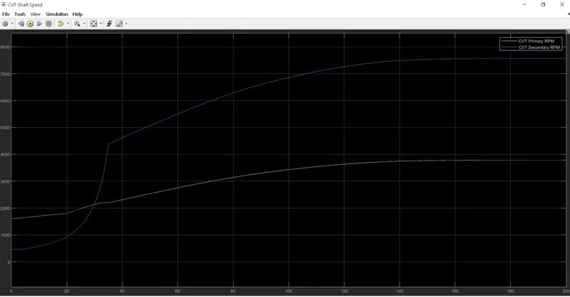
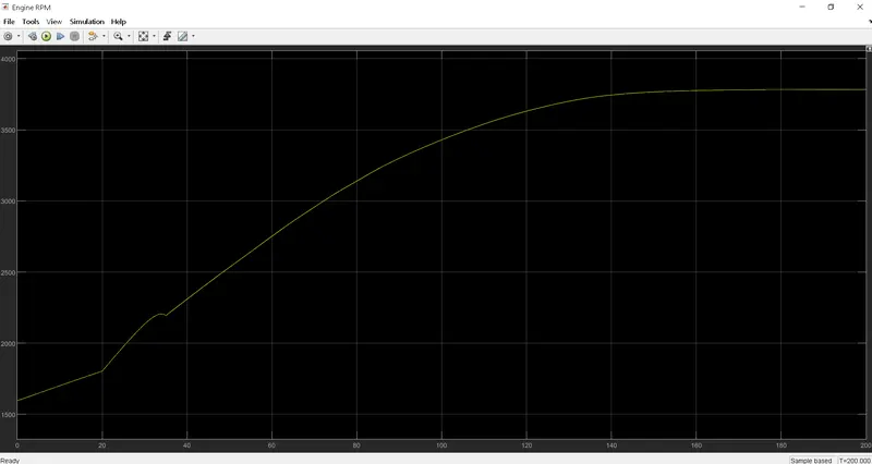
- At last the vehicle speed output is given as feedback to the PS Lookup table(1D) so that we can verify that the velocity of vehicle is changing perfectly when the CVT Ratio changes & vehicle speed is converted to m/s from kmph.
Observation:-
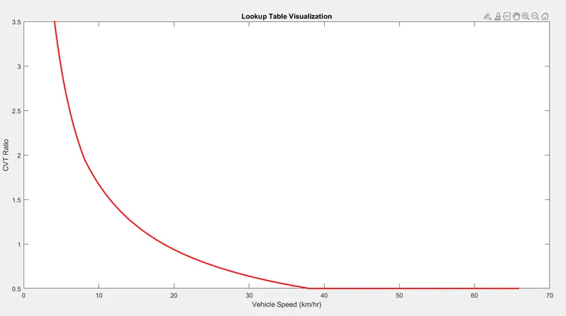
1)Lookup Table Visualization.
2)CVT Ratio:-
3)CVT Shaft Speed:-
4)Engine Speed:-
5)Vehicle speed & Brake, Throttle input:-
c)BAJA ATV Model -Mapped Lookup Table With Dashboard:-The Simulink model of BAJA ATV with dashboard & without dashboard using Lookup Table are same, the only difference is that break & throttle input are controlled by user by using input knob on dashboard & with step block in without dashboard model.
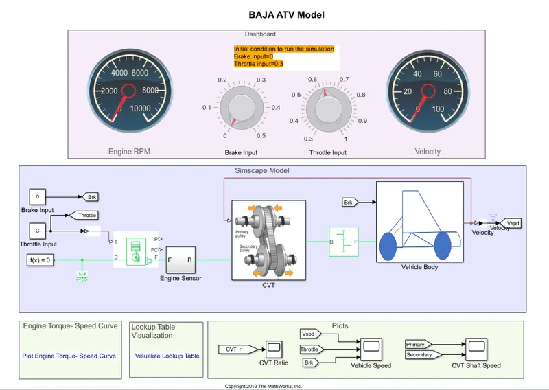
Fig.o BAJA ATV Model -Mapped Lookup Table With Dashboard.
Working procedure:- The model workflow process is same as of"BAJA ATV Model-mapped Lookup table without dashboard", the only difference is that Brake & throttle input are controlled by the user with the knob followed by vehicle speed is given as feedback to the CVT Ratio Lookup table.
Observation:-
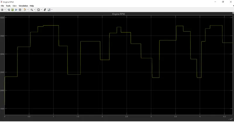
1)Engine Speed:-
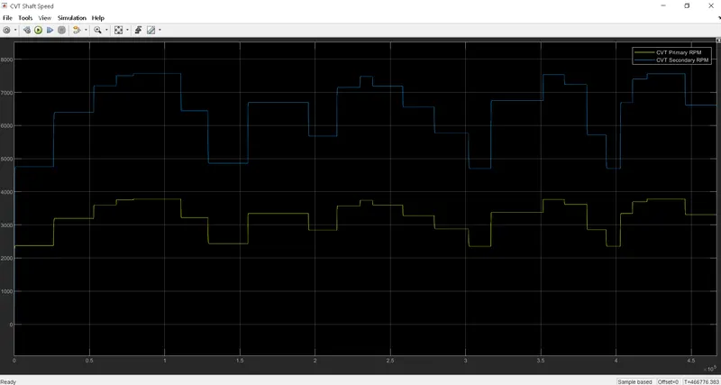
2)CVT shaft speed:-
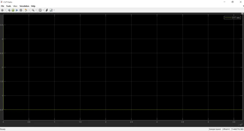
3)CVT Ratio:-
4)Lookup Table Visualization:-
5)Engine Torque-Speed Characterstic curve:-
 Conclusion:-Hence, the given BAJA ATV Model has been studied & simulated successfully from above observations.
Refrences:-
- https://www.mathworks.com/matlabcentral/fileexchange/70576-baja-all-terrain-vehicle-atv-model
- https://en.wikipedia.org/wiki/Baja_SAE