Week - 4
- Implement control logic of a “washing machine” using Stateflow as per given sequence:
- If the power supply is available, the system gets activated
- If the Water supply is not available, stop the process & indicate through LED
- Soaking time should be 200s followed by Washing time of 100s.
- Then rinsing happens for next 20s & dryer runs for 50s
REPORT:
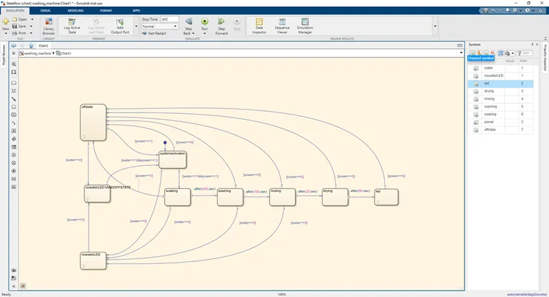
The state flow model for washing machine operation is given below.
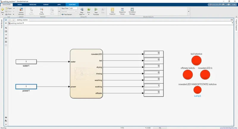
Here, the water and the power are input constants.
The simulink model for washing machine operation is given below.
OPERATION:
Proper flow:
The washing machine operation is demonstrated here in this state flow model. At first, the washing machine will enter to the “system activation” state. After that, it will check whether the water and the power are available. If it is available, then it will pass on to ‘’soaking’’ state. After 200 seconds, the washing machine will jump to “washing” state. After 100 seconds from it, the washing machine will jump to “rinsing” state. After 20 seconds from it, the washing machine will jump to “drying” state. After 50 seconds from it, the washing machine will jump to “led” state, to indicate the completion of washing machine operation.
Case1: If the water is not available during “soaking”,” washing” and “rinsing” states, the flow will instantly jump to “nowaterLED” state, in order to show that there is no water in the washing machine. It will also stop the flow of washing machine, until the water is available to it.
Case2: If the power is not available during any of the states, the flow will instantly jump to “offstate” state, in order to show that there is no power in the washing machine. It will also stop the flow of washing machine, until the power is available to it.
Case3: If the power and the water are not available during any of the states, the flow will instantly jump to “nowaterLED1ANDOFFSTATE” state, in order to show that there are no power and water in the washing machine. It will also stop the flow of washing machine, until the power and water are available to it.
For overcoming all the cases 1,2 and 3, either the water, the power or the water and power should be available respectively to start the washing machine operation from first.
RESULTS:
Kindly simulate the attached model and see every case for detailed results.
Proper flow:
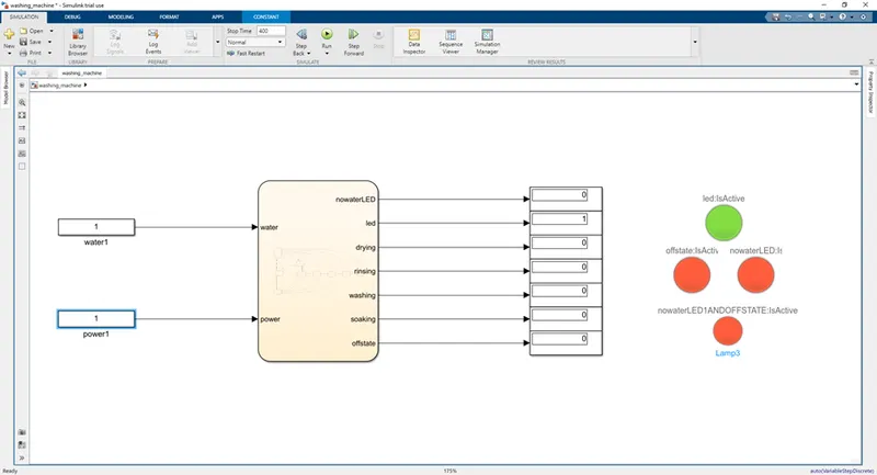
For the proper flow, the previously mentioned operation in description will take place as follow. Finally the “led:IsActive” will glow to indicate the end of washing machine operation.
Here, the water =1 and the power =1;
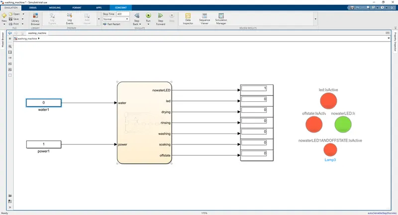
Case1:
For the case1, the previously mentioned operation in description will take place as follow. Finally the “nowaterLED:IsActive” will glow to indicate the absence of water. The LED will not glow, if the water is present.
Here, the water =0 and the power =1;
Case2:
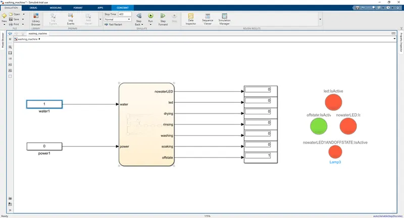
For the case2, the previously mentioned operation in description will take place as follow. Finally the “offstate:IsActive” will glow to indicate the absence of power. The LED will not glow, if the power is present.
Here, the water =1 and the power =0;
Case3:
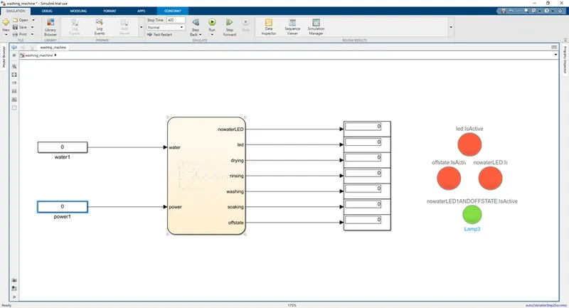
For the case3, the previously mentioned operation in description will take place as follow. Finally the “nowaterLEDANDOFFSTATE:IsActive” will glow to indicate the absence of power and water. The LED will not glow, if the power and water are present.
Here, the water =0 and the power =0;
2. Make a Simulink chart for the “Gear shift” logic as per below conditions:
Speed Range(kmph) Gear
0 to 15 1
16 to 25 2
26 to 40 3
41 to 60 4
Above 61 5
Give speed input while the simulation is running & display the gear number.
.
REPORT:
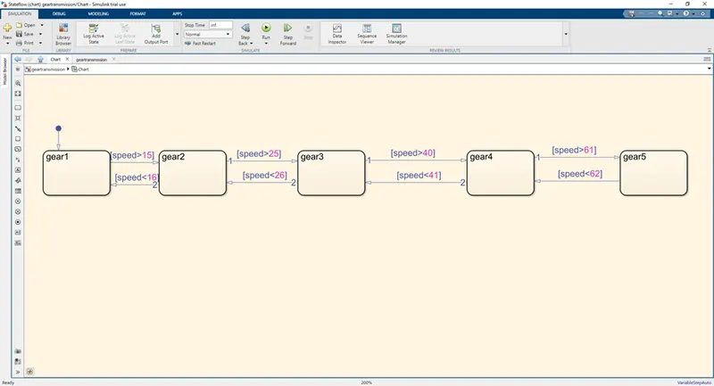
The state flow model for gear transmission operation is given below.
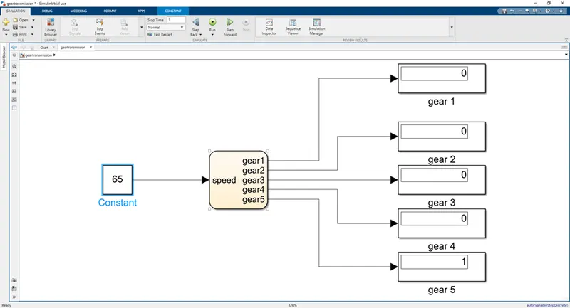
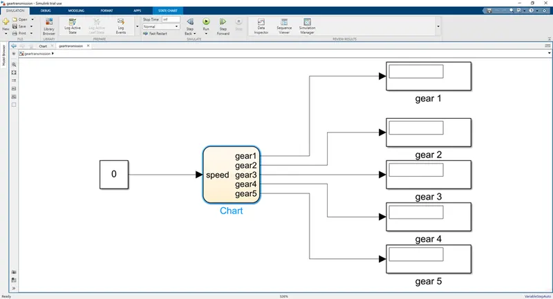
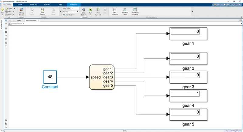
The simulink model for gear transmission operation is given below.
OPERATION:
The state flow will jump for different states based on the input constant to speed.
Speed Range(kmph) STATE
0 to 15 gear1
16 to 25 gear2
26 to 40 gear3
41 to 60 gear4
Above 61 gear5
This can be seen in the state flow model.
RESULTS:
Kindly simulate the attached model and see every case for detailed results.
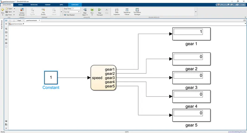
- Gear1:
If the speed is in range (0 – 15 kmph), the “gear1” state is selected, which can also be seen in the display block as follows.
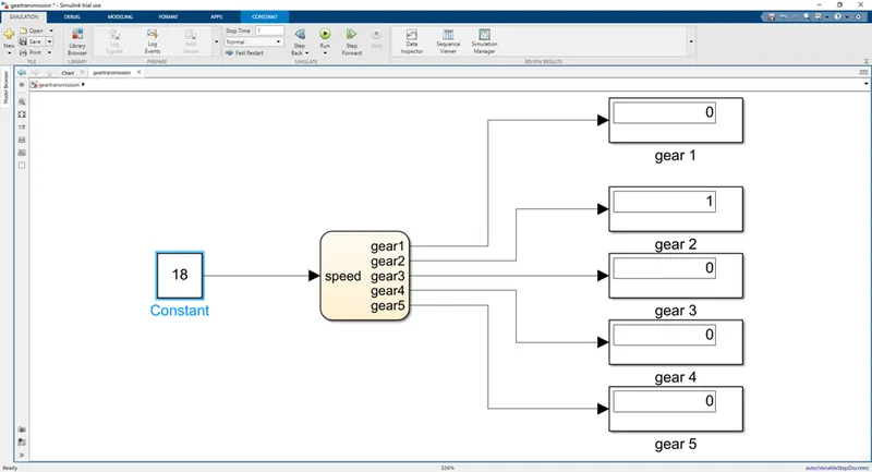
- Gear2:
If the speed is in range (16 – 25 kmph), the “gear2” state is selected, which can also be seen in the display block as follows.
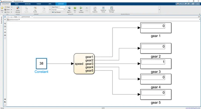
- Gear3:
If the speed is in range (26 – 40 kmph), the “gear3” state is selected, which can also be seen in the display block as follows.
- Gear4:
If the speed is in range (41 - 60 kmph), the “gear4” state is selected, which can also be seen in the display block as follows.
- Gear5:
If the speed is in range (above 61 kmph), the “gear5” state is selected, which can also be seen in the display block as follows.