Project
AIM:
To carry out a system-level simulation of an all-terrain vehicle (ATV). The simulink model is not attached here, since it is available in the link:https://www.mathworks.com/matlabcentral/fileexchange/70576-baja-all-terrain-vehicle-atv-model
INTRODUCTION:
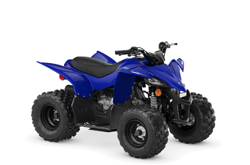
The ATV is All Terrain Vehicle. It is can be used to run in terrains like marsh lands, dry muddy areas, highways, beach areas, low water streams, etc., This machine has the CVT type power transmission system. Hence it has automatic gear ratio changing system. This machine is modelled in Simulink and the case studies are done in it.
SIMULINK MODEL:
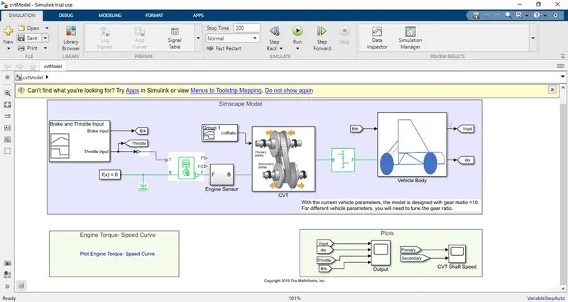
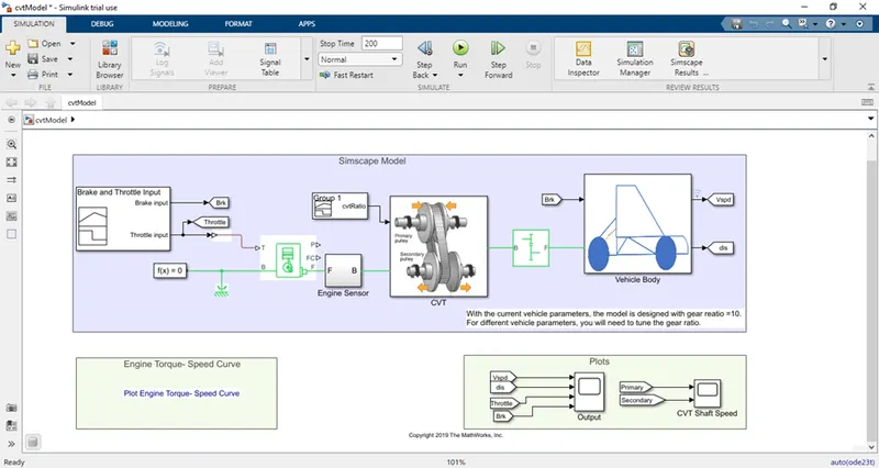
The above model is developed using the various blocks like signal builder for providing the THROTTLE and BRAKE inputs.
The engine block is used to produce the engine rpm, based on the throttle input given to it.
The engine sensor is used to produce the engine rpm output and deliver it to the scope.
This engine output is given to the CVT sub- system.
In CVT sub-system, the variable gear ratio block with inertia is present. This produces the output speed ratio based on the ratio input given to it. The CVT ratio is attached with it, provides the ratio input to variable gear ratio block.
This sub-system also has the speed sensors attached to the primary and the secondary side of the variable gear ratio block and they deliver the outputs to scope.
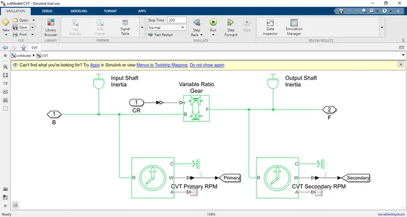
Then, the simple gear block will convert the CVT output rpm to another rpm, based on the gear ratio of it.
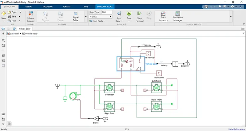
This rpm is given as an input to vehicle body subsystem. The vehicle body subsystem has also the input like brake. The brake signal is applied to the BRAKE block as shown below.
This vehicle body is connected to four tyres with default parameters in it.
The vehicle body outputs the vehicle velocity and the integrate it to produce the distance moved by it. It is also delivered to scope.
OBJECTIVE:
To study the ATV in the following with four cases.
Case 1: CVT ratio of the system is pre – built based on the simulation time and with predetermined speed and brake inputs.
Case 2: The case 1 system with the control using dashboard for the speed and the brake inputs.
Case 3: The system with the CVT ratio generated with lookup table based on the speed input.
Case 4: Dashboard speed and brake inputs to the system with the CVT ratio generated with lookup table based on the speed of the vehicle.
Case 5: Stepped speed and brake inputs to the system with the CVT ratio generated with lookup table based on the speed of the vehicle.
Case 1: CVT ratio of the system is pre – built based on the simulation time and with predetermined speed and brake inputs.
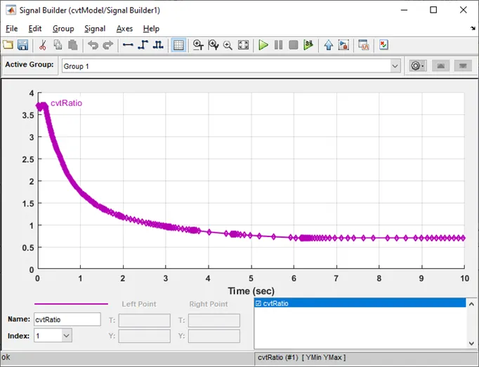
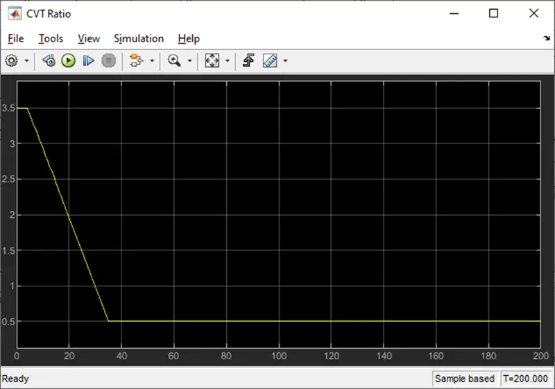
In this case, the CVT ratio is already built based on the simulation time. The system is developed as shown below.
Here, Y axis is “CVT ratio” and X axis is “time”.
The case 1 system is shown below. The simulation is done for the following system using run button.
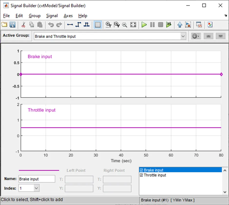
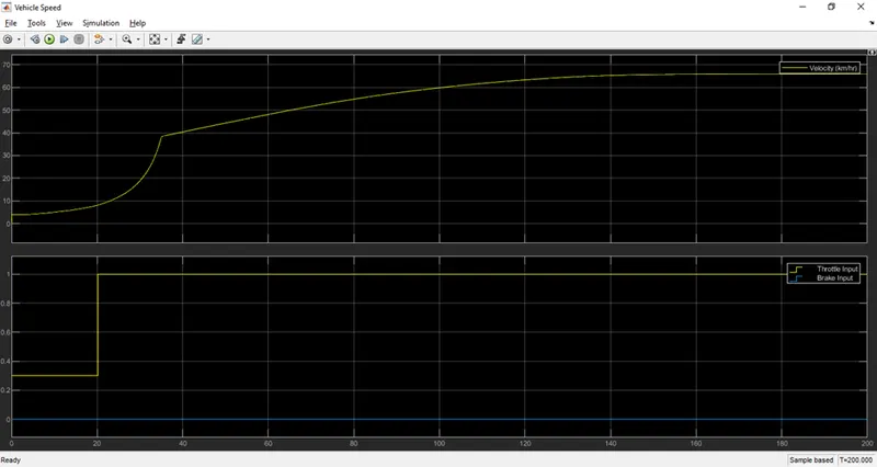
The speed and the brake inputs are predetermined in it as follows.
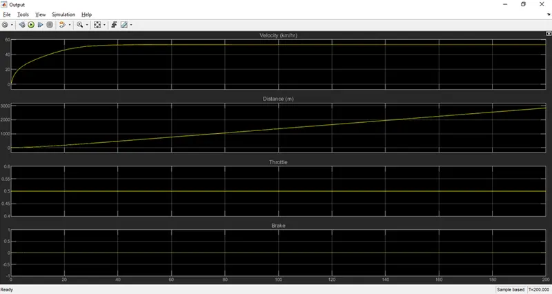
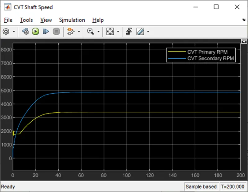
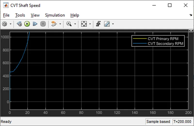
Thus, these signals produce the following outputs as shown below.
Here, X axis is “time”.
Case 2: The case 1 system with the control using dashboard for the speed and the brake inputs.
The system is similar to case 1 system, but the speed and the brake inputs are controlled using dashboard inputs and the output can be seen in the meters. The dashboard inputs are linked with the constant blocks to provide inputs to the system
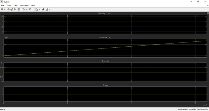
- Here the THROTTLE input is 1 and the BRAKE input is 0, using the rotary switches, given to the system.
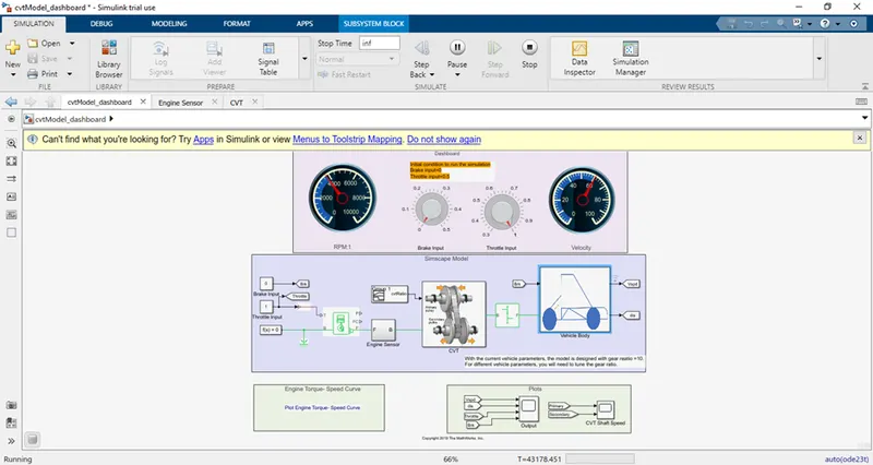 The results (x axis – time) are as follows: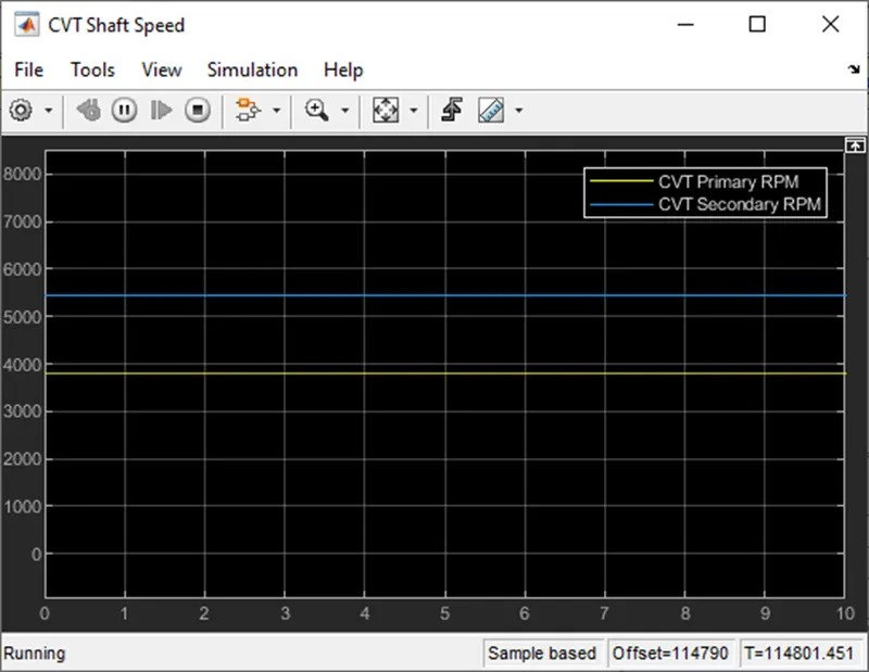
- Here the THROTTLE input is 0.3 and the BRAKE input is 0,using the rotary switches, given to the system
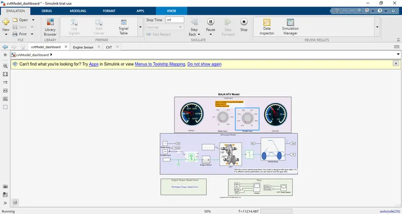 The results (x axis – time) are shown below.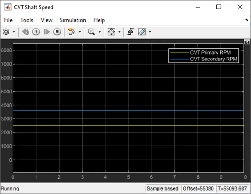
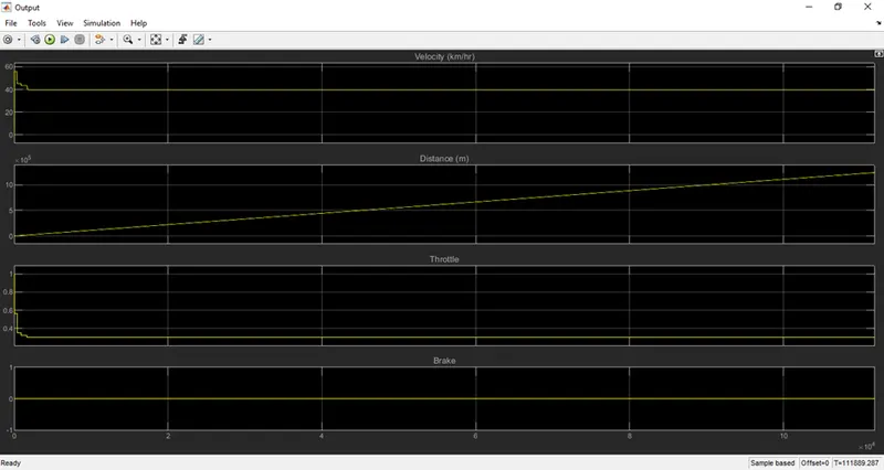
- Here the THROTTLE input is 1 and the BRAKE input is 0, using the rotary switches, given to the system.
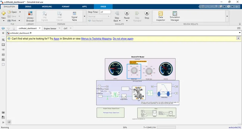
The results (x axis – time) are given below.
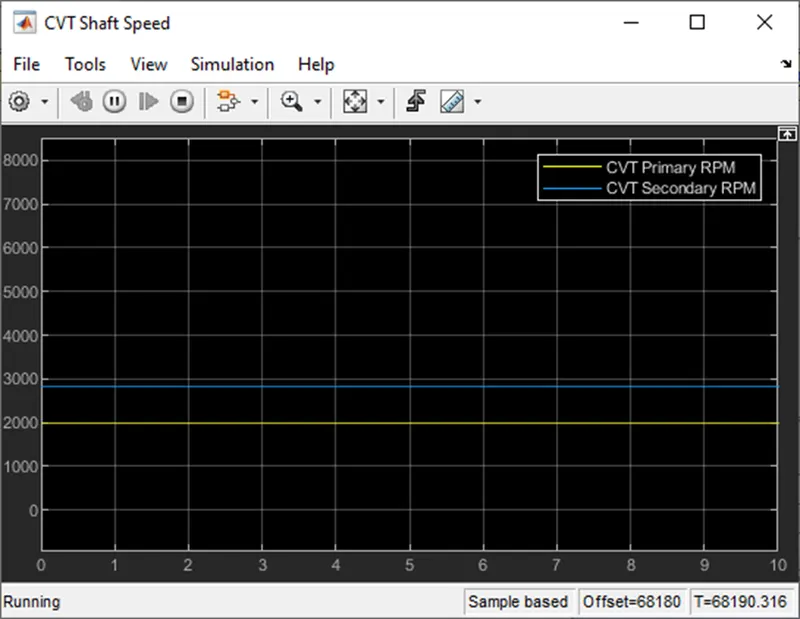
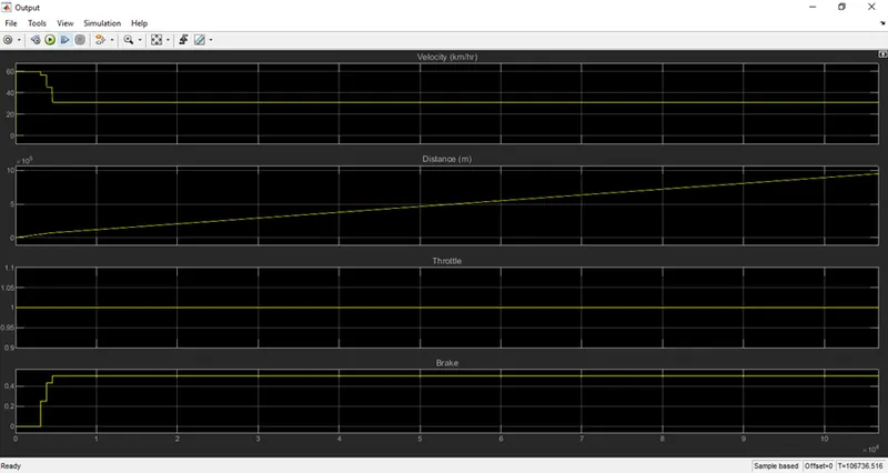
Case 3: The system with the CVT ratio generated with lookup table based on the speed input.
Here, the system is given below. The system is similar to the case 1, but the CVT ratio is not determined based on time. It is determined based on speed. Thus, it will be accurate for any THROTTLE input given to it.
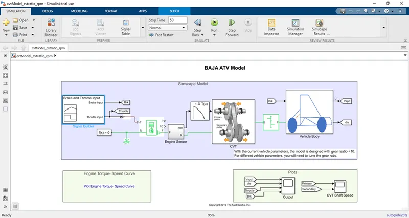
The following inputs are given to the above system.
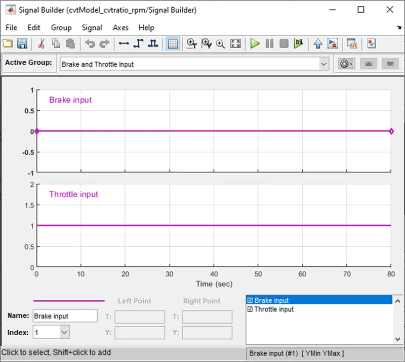
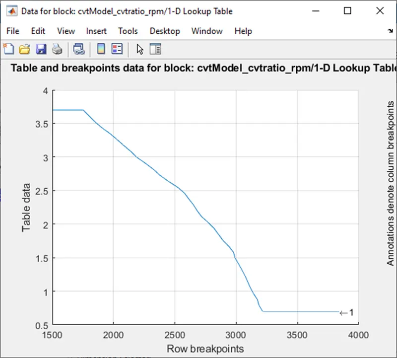
The lookup table for the CVT ratio vs engine rpm is given below. This determines that what CVT ratio should be maintained during the particular engine rpm. Here, the X axis is engine rpm.
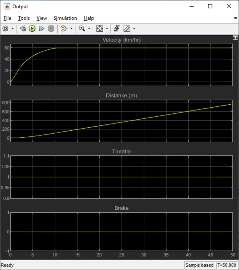
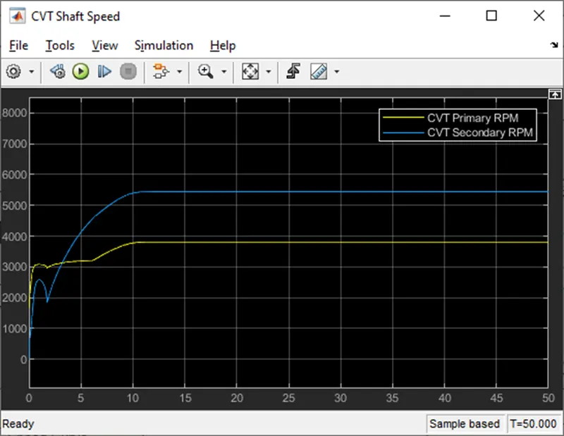
The results (x axis – time) is shown below.
Case 4: Dashboard speed and brake inputs to the system with the CVT ratio generated with lookup table based on the speed of the vehicle.
The system here has the inputs from dashboard and the output can be seen in the meters.
This system is also similar to the case 2. But this system has the CVT ratio based on the vehicle velocity, instead of time based CVT ratio. It is developed using the lookup table.
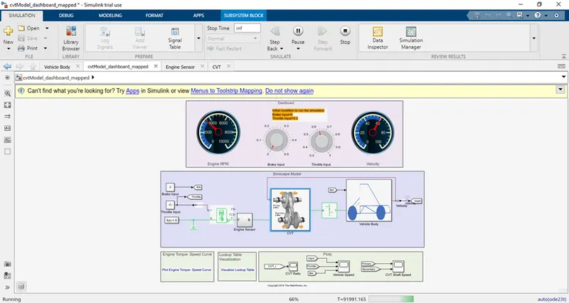
The default inputs are given to the system as shown above and the output in meter are also visualized.
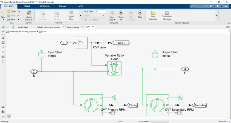
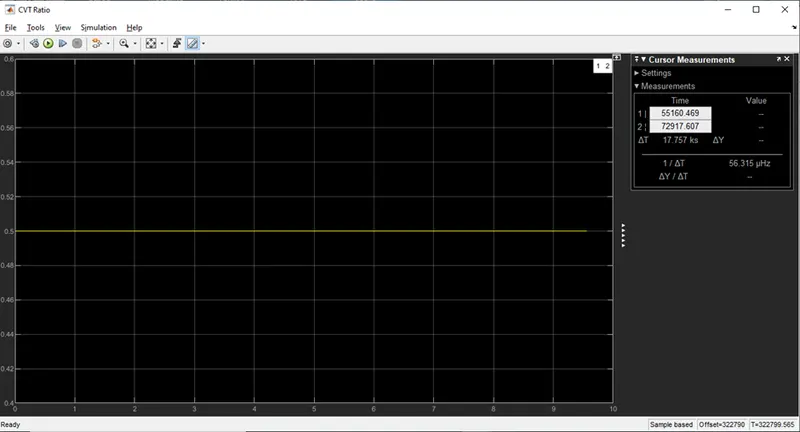
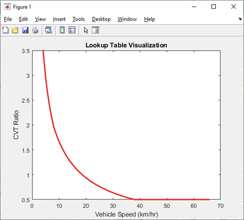
The look up table here is used to produce the CVT ratio based on the vehicle velocity. Thus, the correct CVT ratio is obtained based on the required inputs and outputs. The CVT ratio is shown below.
Here, the look up table is visualized in graph below.
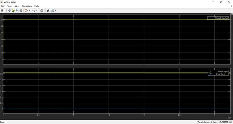
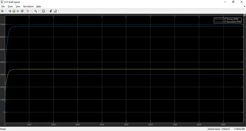
The results (x axis – time) are shown below.
Case 5: Stepped speed and brake inputs to the system with the CVT ratio generated with lookup table based on the speed of the vehicle.
The case 5 system is shown below. The system produces the CVT ratio is generated based on the vehicle velocity. It is similar to case 1. But the THROTTLE and the BRAKE inputs are given as step inputs to system. It has also the lookup table for the CVT ratio vs vehicle velocity.
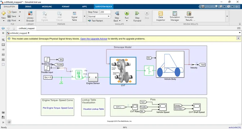
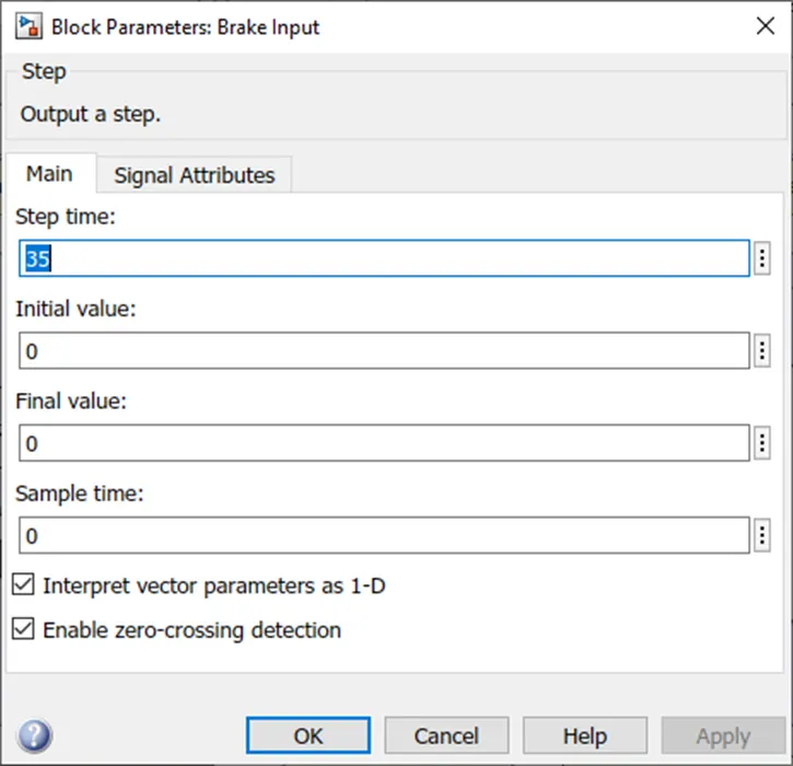
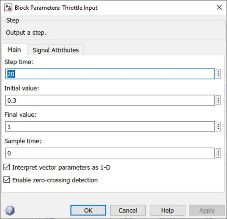
The brake and the THROTTLE inputs are given as the step inputs to system as shown below.
BRAKE INPUT
THROTTLE INPUT
The results (x axis – time) are shown below.
CONCLUSION:
Thus, the system is studied with various case studies, to obtain it characteristics, are done successfully.