Week - 4
AIM: Implement control logic of a “washing machine” using Stateflow as per given condition as per this input and obtain the out put by the lamp
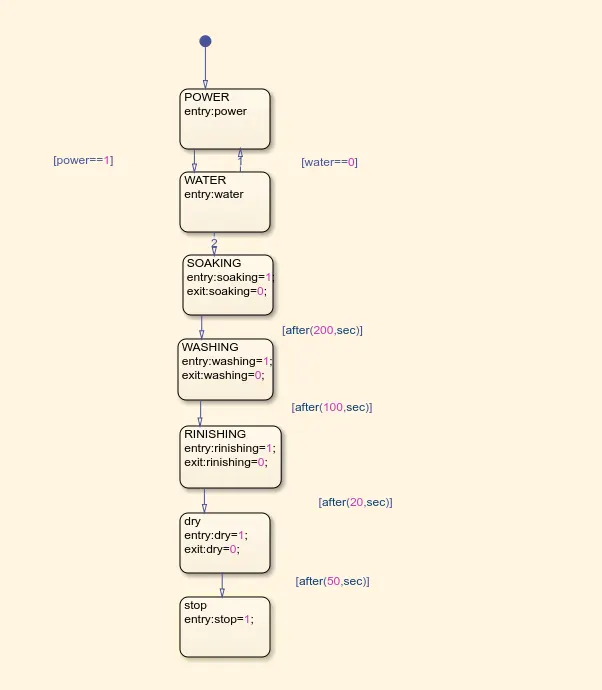
- If the power supply is available, the system gets activated
- If the Water supply is not available, stop the process & indicate through LED
- Soaking time should be 200s followed by Washing time of 100s.
- Then rinsing happens for next 20s & dryer runs for 50s
After all the processes have completed turn on the finished LED
THEORY:
In a front-loading clothes washer...
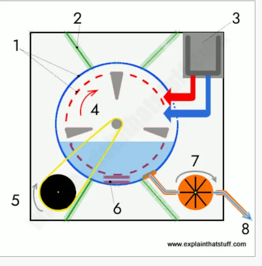
- There's a fixed outer drum (blue) and a rotating inner drum (red) with small holes around its edge. The drums are mounted on a horizontal axis.
- The outer drum is held to the frame of the machine by heavy-duty springs. That's because, when the clothes spin, they can make the drum shake violently; the springs help to absorb the vibrations.
- Hot and cold water enter through the detergent tray at the top.
- The inner drum turns back and forth. The plastic paddles on the inside (shown here by gray triangles) help to slosh the clothes through the detergent and water held by the outer drum.
- An electric motor turns the inner drum, typically using a long rubber belt (yellow).
- A heating element heats the water as necessary.
- When the wash cycle is finished, the pump sucks the water away.
- The water empties down a tube to the drain
In a toploader...
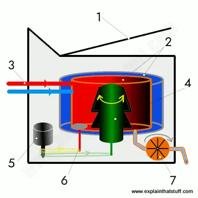
- You lift the lid on top and drop your clothes in from above. We're looking here from one side.
- Just like in a front-loading machine, there's an outer drum (blue) and an inner drum with holes in it (red), but they're mounted about a vertical axis.
- Hot and cold water enter through pipes near the top, passing through the detergent tray and flushing the detergent into the machine.
- During the wash cycle, a large plastic agitator (green) turns around, moving your clothes through the water. Both drums remain stationary.
- The agitator is powered by an electric motor using a rubber belt.
- During the spin cycle, the same electric motor turns the inner drum (red) at high speed, throwing water through its holes into the outer drum.
- When the wash is finished, the pump drains the water from the outer drum.
model:
CONTROL LOGIC:control logic is model system logic using state machine flow chart , truth table
EXPLANATION FOR CONTROL LOGIC OF A WASHING MACHINE USING STATE FLOW:
FIRST WE CREATE A CHART AND ENTER THE GIVEN INPUT CONDITION
if the power supply is availble the system gets activated
if the water supply is not availble stop the process and indicate through tha lamp
if the power supply and water both availble then then process the system and run the machine according to the time given in chat i.e soaking time should be 200sec followed by the washing time of 100 sec after that the system goes to the rinishing process after 20 sec and followed by the dry after 50 sec and the finally the system goest to the stop mode of of operation
WHEN THE WASHING MACHINE IS OFF STATE:
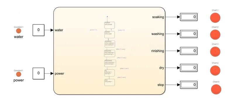
WHEN THE POWER IS AVAILBLE BUT THE WATER SOURCE IS NOT AVAILBLE :
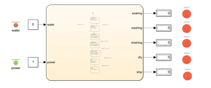
WHEN THE POWER AND WATER BOTH AVAILBLE AFTER 500SEC THE MACHINE IS STOPPED:
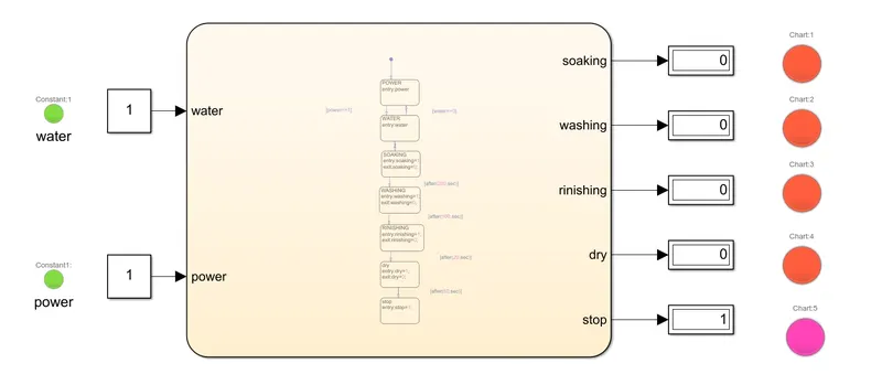
WHEN ONLY WATER SOURCE IS AVAILBLE BUT POWER IS NOT AVAILBLE:
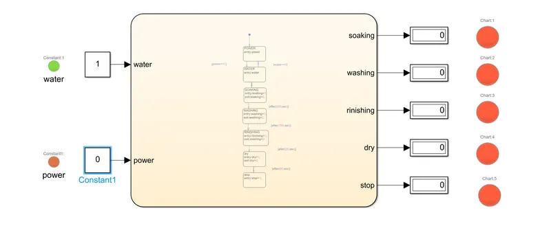
WHEN BOTH POWER AND WATER SOURCE IS NOT AVAILBLE:
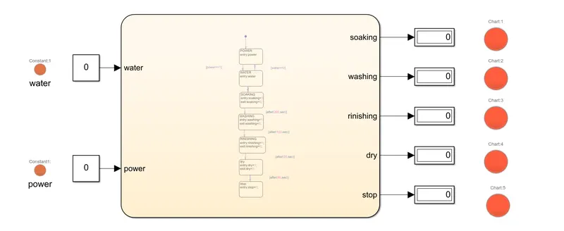
GEAR SHIFTING MECHANISM:
aim : implement the control logic of a gear and run simulation according to given condition :
Speed Range(kmph) Gear
0 to 15 1
16 to 25 2
26 to 40 3
41 to 60 4
Above 61 5
Give speed input while the simulation is running & display the gear number.
CONTROL LOGIC FOR GEAR MECHANISM :
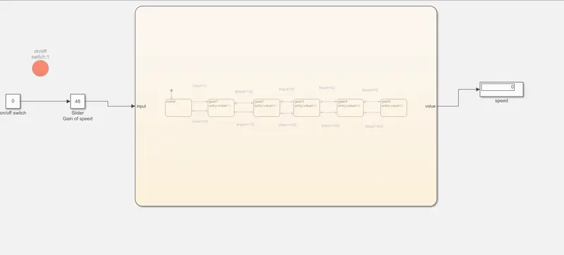
when the speed is given as input with slider gain according to slider gain the speed volues change based on speed volues the gear mechanism wil work
i.e th speed is zero it is in stop condition when the spped increse by using slider gain if the volue of speed is
speed>0and the speed is less than 15 it is run in first gear and the speed is more than than60 it is run in gear 5 based on this logic control logic is developed on the matlab and it is chat mode
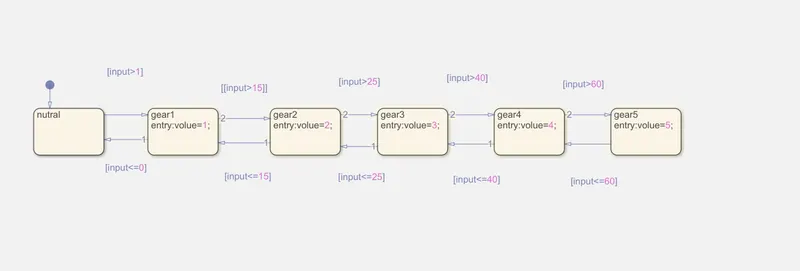
intilly the on/off switch is used when this volue is 1 it is active state when this volue is zero it is off state
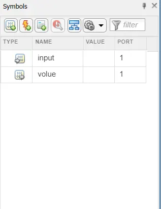
by using symbol plane the input and output ports are created in a chat mode :
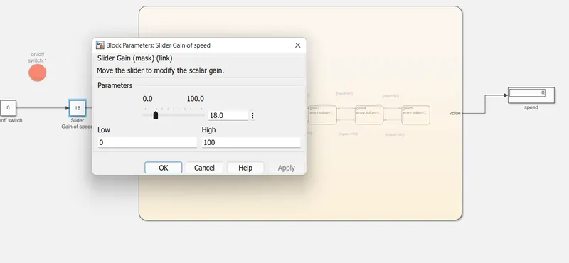
WHEN THE SWITCH IS ZERO STATE THE SPEED IS ZERO IRRESPECTIVE OF THE SLIDER GAIN :
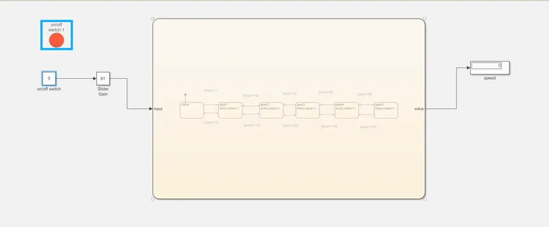
USING SLIDER GAIN CHANGING THE SPEED:
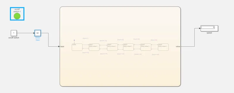
WHEN THE SWITCH ACTIVE LAMP SHOWS GREEN AND THE VOLUE SPEED IS 91 IT IS RUNNING IN GEAR 5:
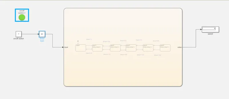
THE VOLUE OF SPEED IS 51 I.E RUNNING IN GEAR4:
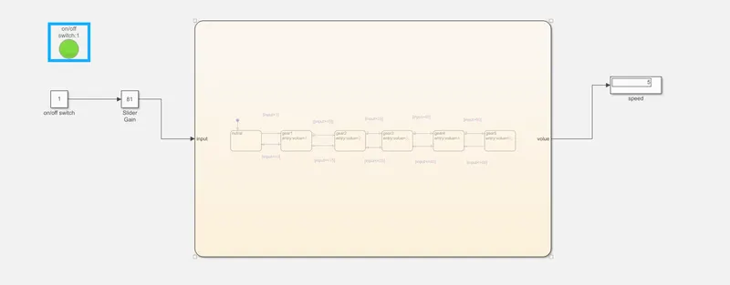
SPEED IS ABOVE 6O RUNNING IN GEAR 5:
conclusion: according to given questions all condition are observed and verified and the results are shown ;