Project
AIM: to study and analsye the system level model simulation of an BAJA(ATV) model using simulink and prepare a proper technical report on its properties with reference to all different model
objectives:
to prepare a technical report on baja (ATV ) model and explain the model properties using look up table and with out using the lookup table and comments the results
understnd the different types of baja ATV models:
THEORY:
Baja SAE is an collegiate design series competition run by the society of automotive engineer (SAE International). Teams of students from universities all over the world design and build small off road cars The cars all have engines of the same specifications. As of 2018 the engine has been an unmodified Briggs & Stratton Model 19 Vanguard engine single-cylinder with a displacement of 305cc and power output of approximately 10 bhp (7.5 kW).
The goal in Baja SAE racing is to design, build and race off-road vehicles that can withstand the harshest elements of rough terrain. The vehicles used in Baja SAE racing are often similar in appearance to dune buggies. Before 2007, the events were called "Mini Baja."
Each year as many as 141 Baja cars are entered in the Baja SAE events across the US and around the world. International events are endorsed by SAE International and are held in Brazil, Korea, South Africa and México.
All cars must adhere to SAE International's rules, and pass SAE's technical inspection and judging; a car may not race until all safety inspections are passed. Small engine manufacturer sponsors Baja SAE teams by providing the SAE sanctioned engine free of charge, at a replacement rate of one engine for every two years in competition.
There are multiple dynamic events, photographed by Official SAE Photographer Jethro Gaines of J. Gaines Studio, usually four per event, as well as a single four-hour endurance race. The dynamic events include hill climbe sled pulls, maneuverability events, and suspension & traction events. Previously the cars had to be able to float and propel itself on water under its own power. This was changed from the 2012 competitions onward due to safety concerns.
THE COMPONENTS USED IN THIS SIMULATION :
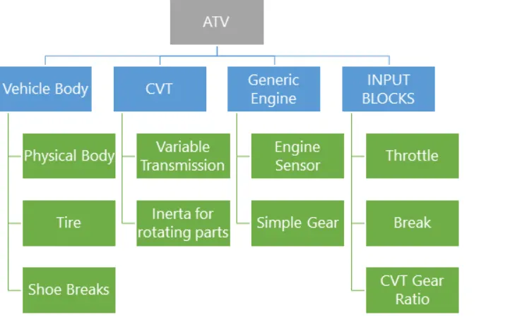
GENERIC ENGINE BLOCK:
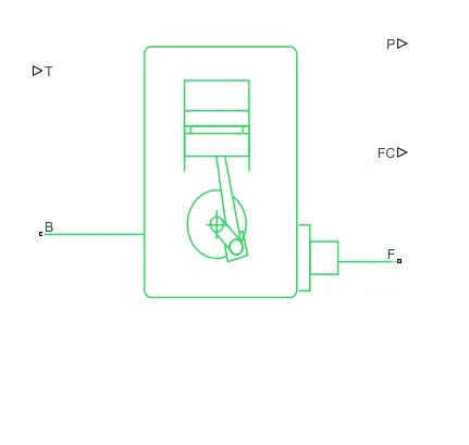
the generic engine block represent a general internal combuction engine a system-level model of spark-ignition and diesel engines suitable for use at initial stages of modeling when only the basic parameters are available. Optional idle speed and red line controllers are included.
The throttle input signal T :
lies between zero and one and specifies the torque demanded from the engine as a fraction of the maximum possible torque. If the engine speed falls below the Stall speed, the engine torque is blended to zero. If the engine speed exceeds the Maximum speed, the simulation stops and issues an error message.
connectionsF and B -
are mechanical rotational conserving ports associated with the engine crankshaft and engine block, respectively.
Connections P and FC-
are physical signal output ports through which engine power and fuel consumption rate are reported.
SIMPLE GEAR :
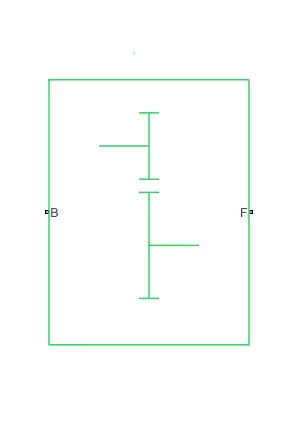
simple gear Represents the fixed-ratio gear or gear box ,No inertia or compliance is modeled in this block.
You can optionally include gear meshing and viscous bearing losses.
Connections
B (base) and F (follower) are mechanical rotational conserving ports. Specify the relation between base and follower rotation directions with the Output shaft rotates parameter. Optionally include thermal effects and expose thermal conserving port H by right-clicking on the block and selecting Simscape block choices to switch between variants.
CVT TRANSMISSION:
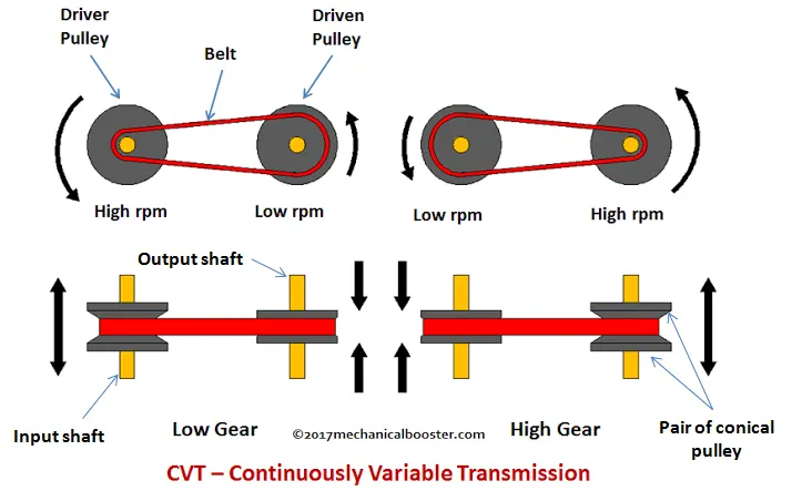
A continuously variable transmission system is a type of automatic transmission in which an arrangement of pulleys and belts made it possible for a drive to achieve n-number of continuous gear ratios within a range (depends on the design).
A continuously variable transmission in a vehicle senses the accelerator input with engine load and get shifted to the desired speed or torque gear ratio automatically, in other words we can say that a cvt transmission is one of the simplest types of automatic transmission that provides continuous uninterrupted power within a specified range of speed and torque ratios.
To understand how it actually work first lets understand cvt’s construction.
VEHICLE BODY:
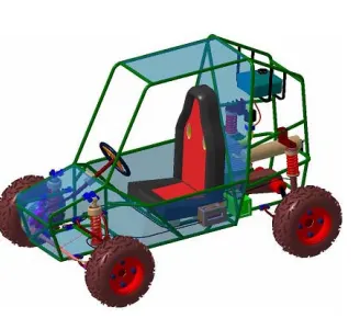
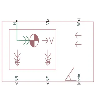
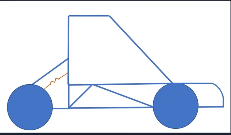
The Vehicle Body block represents a two-axle vehicle body in longitudinal motion. The vehicle can have the same or a different number of wheels on each axle. For example, two wheels on the front axle and one wheel on the rear axle. The vehicle wheels are assumed identical in size. The vehicle can also have a center of gravity (CG) that is at or below the plane of travel.
The block accounts for body mass, aerodynamic drag, road incline, and weight distribution between axles due to acceleration and road profile. Optionally include pitch and suspension dynamics. The vehicle does not move vertically relative to the ground.
The block has an option to include an externally-defined mass and an externally-defined inertia. The mass, inertia, and center of gravity of the vehicle body can vary over the course of simulation in response to system changes.
NR =near axle normal force
NF = front axle normal force
BETA= road incline angle
V = longitidunal velocity
w=head wind speed
H= horizantal motion
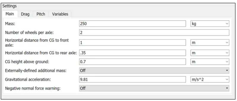
SETTING FOR THE VEHICLE BODY:
DOUBLE SHOW BRAKE:
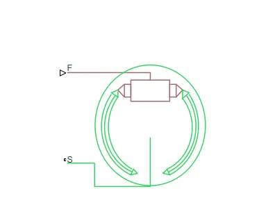
Represents a brake arranged as two pivoted rigid shoes symmetrically installed inside or outside a drum and operated by one actuator. The actuator force causes the shoes to exert a friction torque on a shaft connected to the drum.
Connection S-
is a conserving rotational terminal associated with the drum shaft.
Connection F-
is a physical signal port representing the force input to the actuator. Positive force creates friction torque that resists shaft rotation. Optionally include thermal effects and expose thermal conserving port H by setting Thermal port to Model.
TYRES AND BRAKE:
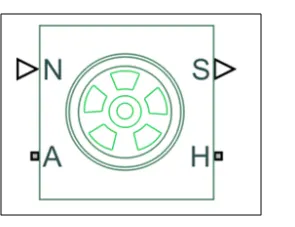
the vechile body is connected to 4 tyres each per axle to move the vehicle according to input to the axle
where n-normal force
s- is the tire slip
a - axle
h- mechanical translational ports associated with the tyres
STUDY THE BAJA ATV MODEL WITH OUT A DASHBOARD
SIMULATINK MODEL:
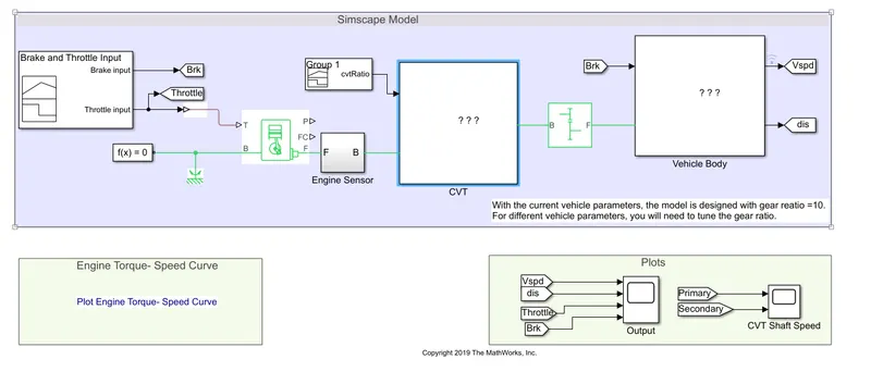
CVT MODEL OF SET UP BLOCK
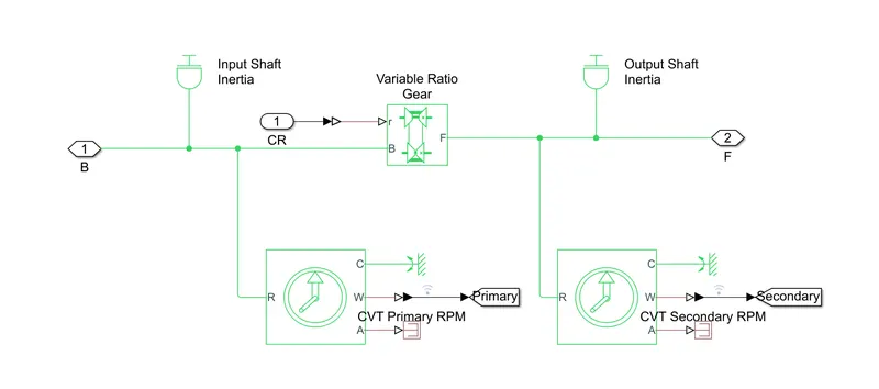
VEHICLE BODY
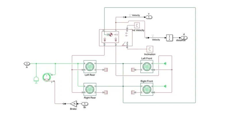
INPUT: one signal builder block is used to create a signal for throttle and brakes and another one is used to create the needed cvt ratio
THROTTLE AND BRAKE INPUT
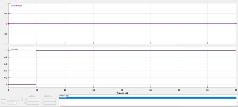
when we applied the brake inputs are zero and the and the throttle input is zero from 0-10 sec after that it is one from 10-80 sec it is a given volue
CVT GEAR RATIO
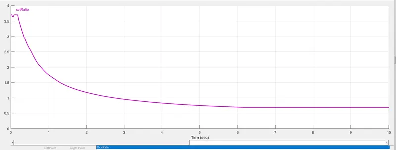
cvt gear ratio volues changes entirely over the period of time intially it is around 3.8 after that it is continiously decresing and finally at a constant volue of 0.8
THE ENGINE TORQUE SPEED CHARACTERSTIC CAN BE GIVEN AS FOLLOWS
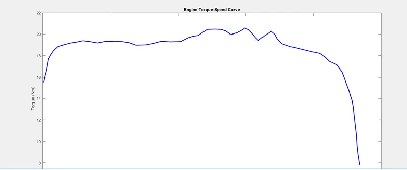
OUT PUT RESULT OF AN THROTTLE AND BRAKES AS SHOWN BELOW
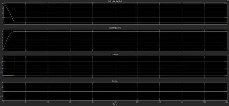
when the throttle is zero the speed gradually incresing and attains a naximum speed when the throttle is at one and after that the throttle is constant and then speed is gradually decresing and finally the speed is in constant mode
the brake input is constant for entire region and hence it does not effect the velocity
CVT PRIMARY AND SECONDARY SPEED:
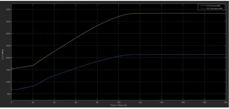
the graph shows the variation in angular velocities primary input and secondary output shaft of the variable transmission system this volues differ from the gear ratios i.e if the gear ratio changed the volues of the output also changed
STUDY OF BAJA ATV MODEL WITH A DASH BOARD :
SIMULINK MODEL:
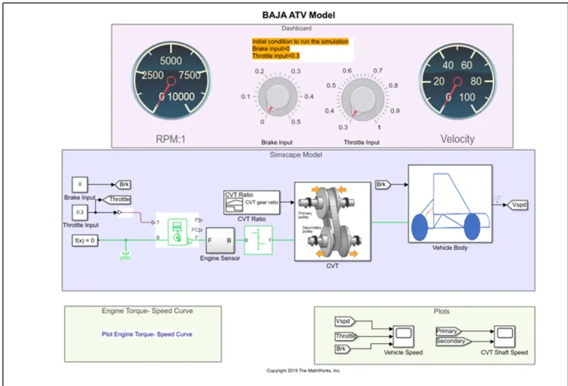
this model is same as the cvt model ,but here the input is given through the dash model there are two input one is brake and the throttle both are connected to the constnant block which provide the input while the model is running for infinite time this help us to create various scenarios while the simulation is running
ENGINE SENSOR:
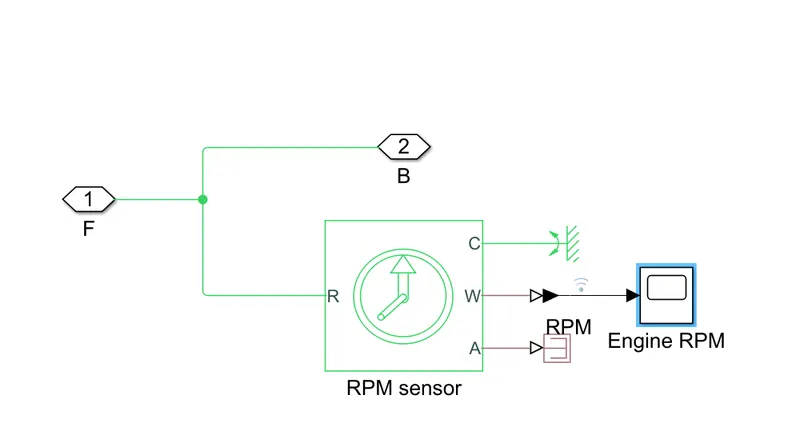
the block represents an ideal mechanical roatational motion sensor that is a device that converts an across variable measured betwen two mechanical roatational nodes into a control signal proportional to angular velocity or angle the sensor is ideal since it does not account for inertia ,friction ,delay, energy consumption and so on.. connection r and c are mechanical roatational conserving ports and connection w and a are physical signal output ports for velocity and angular displacement respectively
CVT MAPPED MODEL:
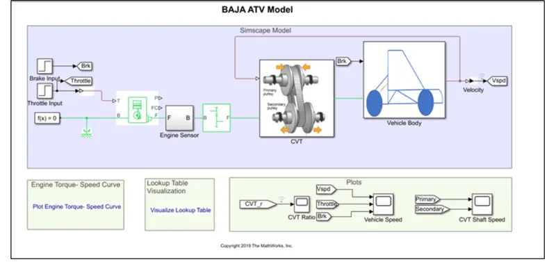
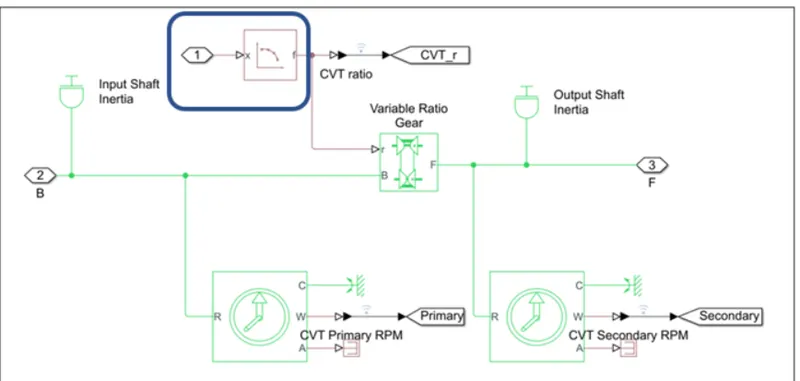
here we can observe the cvt gear ratio is not given through an input signal builder rather here we are using look up table as shown
OUTPUT RESULTS:
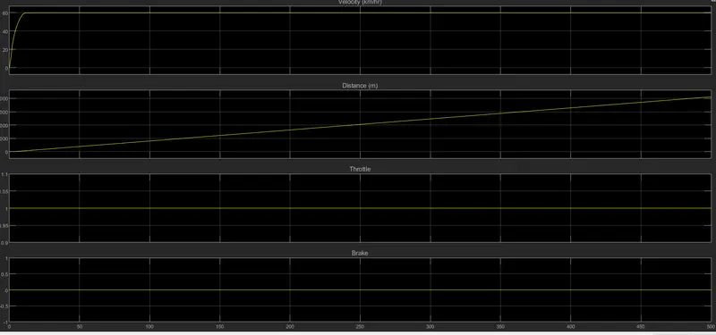
as we can obseve the resuts from above diagrams when the brake and throttle as applied as zero in this case the distance and the velocity we can obseved as distance incresed gradually and the as same as velocity as velocity intially incresed gradually and then it goes to a constant volue
CVT SHAFT SPEED :
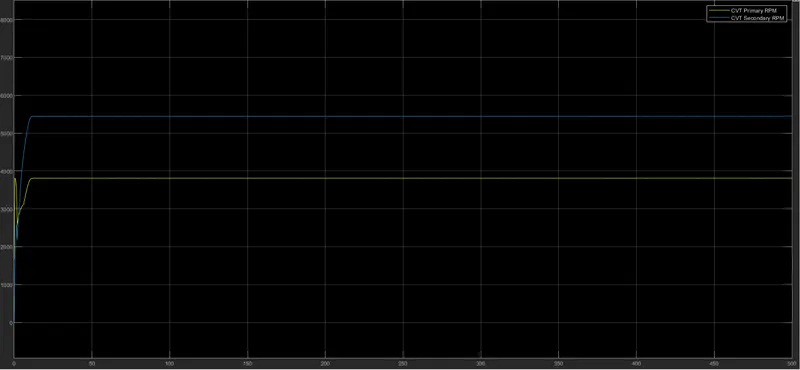
as we can observe from the above the speed of driver shaft and the driven shaft one is folled by the other
ENGINE SPEED :
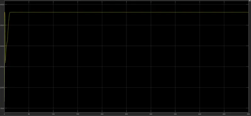
as we can observe from the above the engine speed is gradually increses up to acertain level and after that the engine speed attain a maximum volue and it is remains same for the simulation we are running for an infinite time
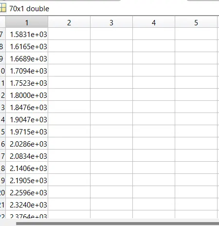
SPEED VECTOR
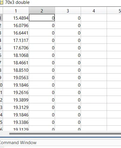
TORQUE VECTOR:
LOOKUP TABLE VISUALIZATION:
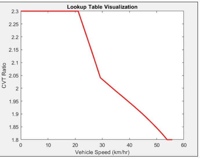
here it is represent the look up table and the vehicle speed is working as the input vector and the cvt ratio is the out put obtained based on the relation described by the user to evoluate the cvt
the ps look up table block computes an approximation to some function f=f(x) given data vector x and f both the input and the output are physical vector
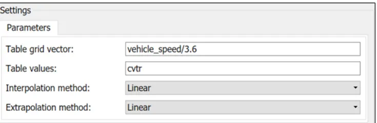
in this way we can model a continiously varying transmition based on the vehicle speed
CONCLUSION: simulation of baja ATV using CVT is simulated in two ways to viusulaize the effect of CVT on vehicle velocity and rpm .based on this we can simulate multipule situation and design using of tht particular model