Week -2
AIM:
- to make a simulink model of door bell using solenoid block.
using thermistor to sence the temperature of a heater and turn on and turn off of fan
SIMULINK MODEL OF DOOR BELL:
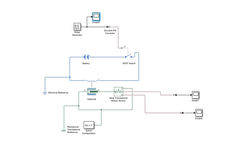
EXPLANATION:
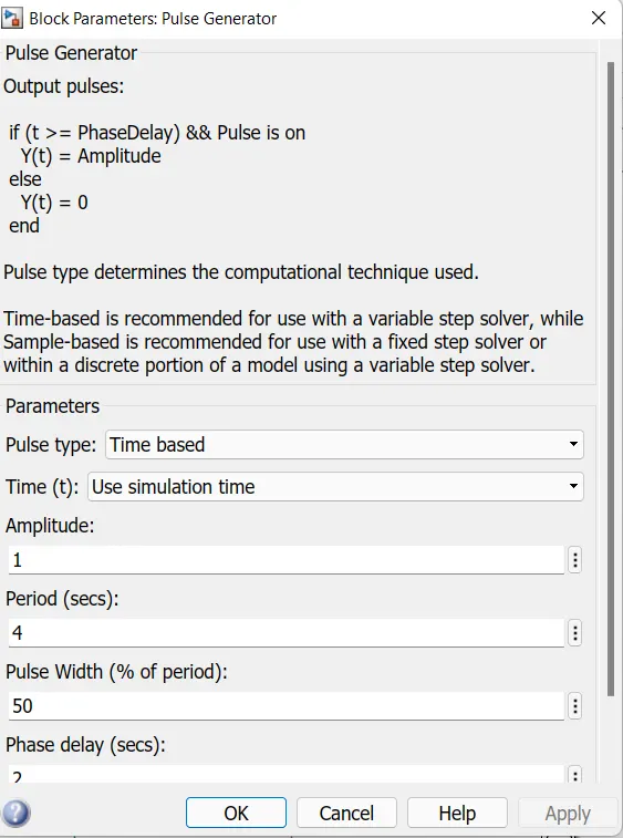
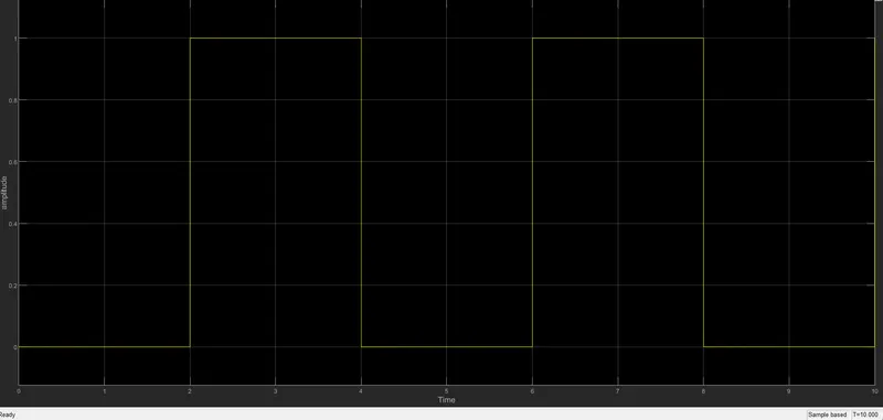
pulse wave generator is used to create pulses at an regular intervel of time. the time period and pulse width and delay period and amplitude of the wave form as menctioned below
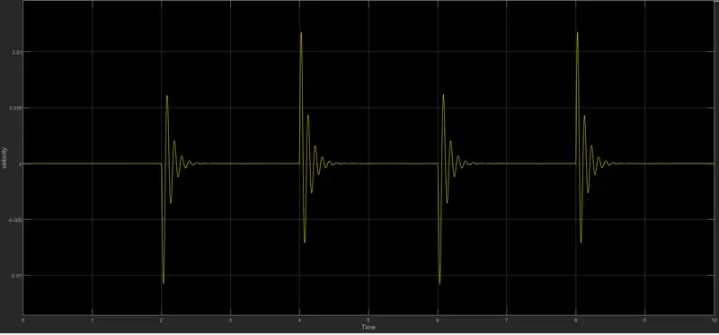
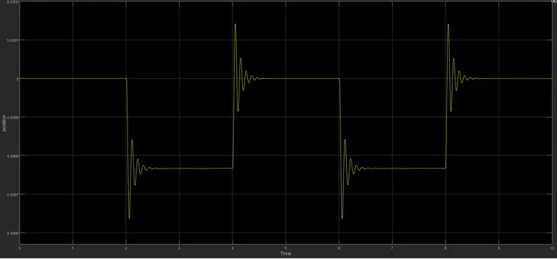
the pulse wave generator is simulink signal so it is converted by using simulink to ps converter and it is connected to vT ,spst represents a Single-Pole Single-Throw (SPST) switch controlled by an external control signal vT. If vT is greater than the threshold, then the switch is closed, otherwise the switch is open. If you select Infinite for the Battery charge capacity parameter, the block models the battery as a series internal resistance and a constant voltage source. POSSITIVE TERMINAL IS CONNECTED TO SWITCH AND NEGATIVE TERMINAL CONNECTED ELECTRICAL REFERENCES.the solenoid block is connected to switch and battery and the c port is a common port which is conneted to mechanical references and the port is connected the ideak translatonal motor sensor input port and to observe the movement of the plunger and the scope is coonected to ideal translational motor sensor to obseve the output wave forms
each physical system represented by a simscape network of function requires solver setting configuration for simulation
INPUT WAVEFORMs:
OUTPUT WAVE FORMs:
Use a thermistor to sense the temperature of a heater & turn on or turn off the fan as per the below conditions:
AIM:TO CREATE A MODEL OF THERMISTOR TO SENCE THE TEMPERATURE OF A HEATER AND TURN ON AND TURN OFF THE FAN
CONDITION:
Temperature source:
20 °C from 0 to 10 seconds,
27 °C from 10 to 30 seconds,
23 °C from 30 to 50 seconds
Fan conditions: ON if the temperature above 25 °C, OFF otherwise
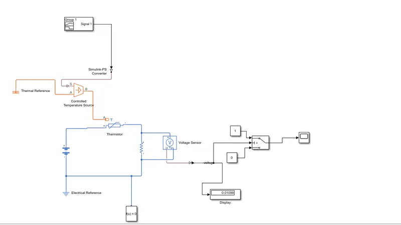
MODEL:
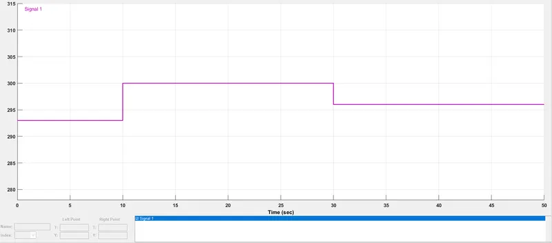
INPUT SIGNAL:
INPUT TEMPERATURE/TIME
X AXIS [0 10 10 30 30 50]
YAXIS [293 293 300 300 296 296]
working procedure:
inputs are given to signal builder and the signal builder is connected the controlled temperature source to maintain a controlled temperature difference regardless of the heat flow rate. The temperature difference is set by the physical signal port S. A positive temperature difference causes the temperature at port B to be greater than the temperature at port A.and it is connected to a thermistor an NTC thermistor using the B-parameter equation. The resistance at temperature T is given by R(T) = R0*exp(B*(1/T-1/T0)) where R0 is the Nominal resistance at the reference temperature T0, and B is the Characteristic temperature constant. The temperature T of the thermistor is governed by the equation m*c*dT/dt = Q where Q is the net heat flow into port A, m is the mass and c is the lumped specific heat capacity. The thermal mass m*c is calculated from the Thermal time constant t_c and the Dissipation factor K_d using the equation m*c = K_d*t_c.
thermistor is connected in seiries to the resistor voltage-current (V-I) relationship for a linear resistor is V=I*R, where R is the constant resistance in ohms.
The positive and negative terminals of the resistor are denoted by the + and - signs respectively. By convention, the voltage across the resistor is given by V(+)-V(-), and the sign of the current is positive when flowing through the device from the positive to the negative terminal. This convention ensures that the power absorbed by a resistor is always positive. and the voltage across the resistor is senced by the voltge sensor represents an ideal voltage sensor, that is, a device that converts voltage measured between any electrical connections into a physical signal proportional to the voltage.
Connections + and - are conserving electrical ports through which the sensor is connected to the circuit. Connection V is a physical signal port that outputs voltage value. and the physical signal is converted in to ps simulink converter and it is connected to switch port 2
switch consist of 3 ports port1 port2 port 3 and it has a threshold volue when the temperature volue is set to 298 and we have to find the voltage acroos the resistor i. is set to a threshold voltage across the switch after setting this threshold voltge in the switch and the input connect to a signal builder source after this running the simulation when that threshold volues satifies witjh this signal builder and the temperature is above 25degree port 2 pass the signal to the port 1 from 0 to 10 second the temperature i below 25 degree and fan is off condition port 2 pass the signal to port 3 from 10 to 30 second the voltage is greater than 25 the port 2 pass the signal form port2 to the port 1 from 30 to 50 second the the temperature is below 25degree and the port 2 pass the signal to port 3 and it is off condition this out are shown in a scope bys the scope block
OUTPUT PLOTS:
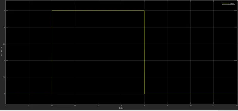
hence above required conditions are obtained by using simulink