Week - 4
(1) control logic of a “washing machine” using Stateflow ::
>>OBJECTIVES:
> To implement the control logic of a washing machine using the state flow as per given sequence
a)If the power supply is available, the system gets activated
b)If the Water supply is not available, stop the process & indicate through LED
c)Soaking time should be 200s followed by Washing time of 100s.
d)Then rinsing happens for next 20s & dryer runs for 50s
e) After all the processes have completed turn on the finished LED.
>> BLOCKS Required:
>stateflow: Stateflow is a control logic tool used to model reactive systems via state machines and flow charts within a Simulink model.
>constant: gives an input to the system.here we are using for switch ON/OFF condition
>Display: displays the out put values of the system.
>Toggle switch; The Toggle Switch block toggles the value of the connected block parameter between two values during simulation. For example, you can connect the Toggle Switch block to a Switch block in your model and change its state during simulation.
> Lamp: The Lamp block displays a color that indicates the value of the connected signal.
>> BLOCK DIAGRAM REPRESENTATION:
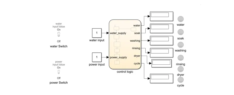
control logic of a 'washing machine' using state flow
Parameters:
1) water input is provided by value '1'(water supply ON) and '0' (water supply OFF)
2) power input is provided by value '1' (power ON) and '0' (power OFF)
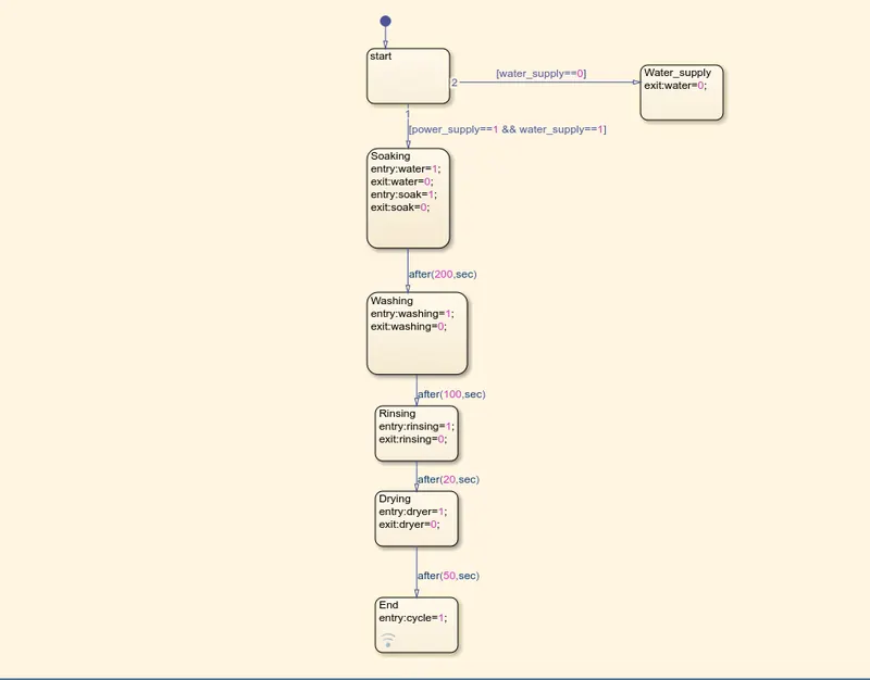
>> chart diagram::
>>symbol space:
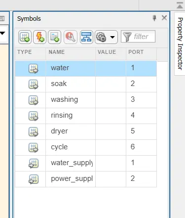
> Here the given water,soak,washing,rinsing,dryer,cycle are the outputs of the state flow
> water_supply,power_supply are given as inputs to the state flow
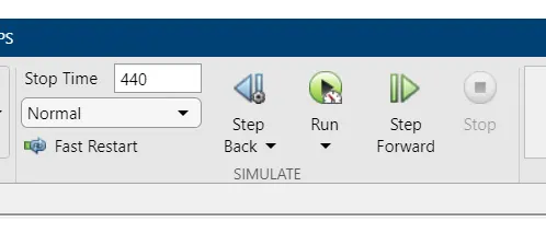
>Simulation Running Time:
> here run time is given as 440 sec which is an enough time to run all the simulation
>> OUTPUTS::
> By running the simulation we are getting different outputs as per given inputs.
(1)The power supply is available, the system gets activated automatically
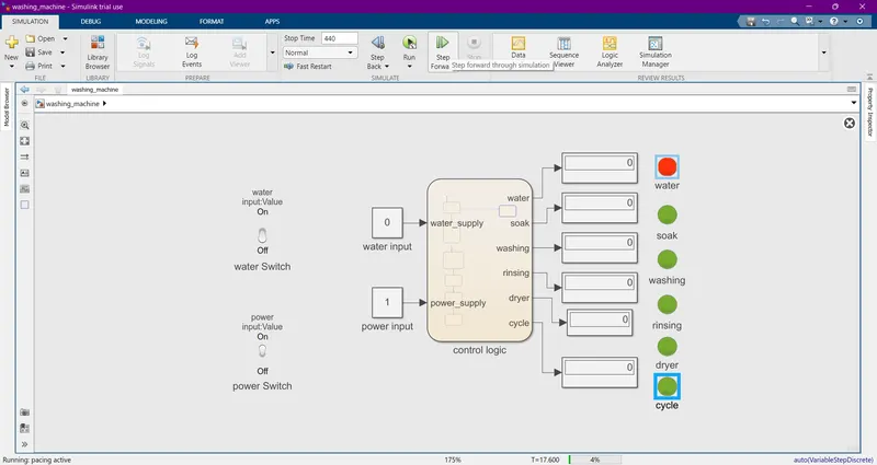
(2)(a) when water supply is OFF:
>here we are switching off the water supply by an Toggle switch whcih was provided in the system.
>The output is
Conditions:
> From the above fig we observed that the 'RED' when the water supply is not given to the system.
> All the reamining whcih shows"green" are active in the system
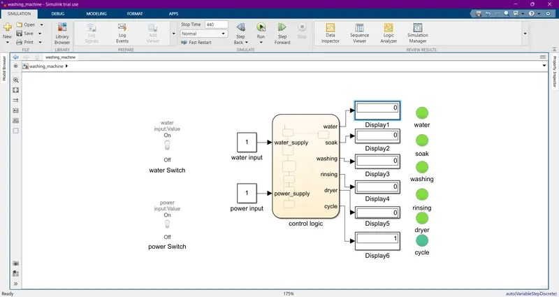
(b)when water supply is ON:
> When the water supply ON's the signal"changes" into 'green' colour and the system runs;
(3) Soaking time should be 200s followed by Washing time of 100s.
(a) soaking process:
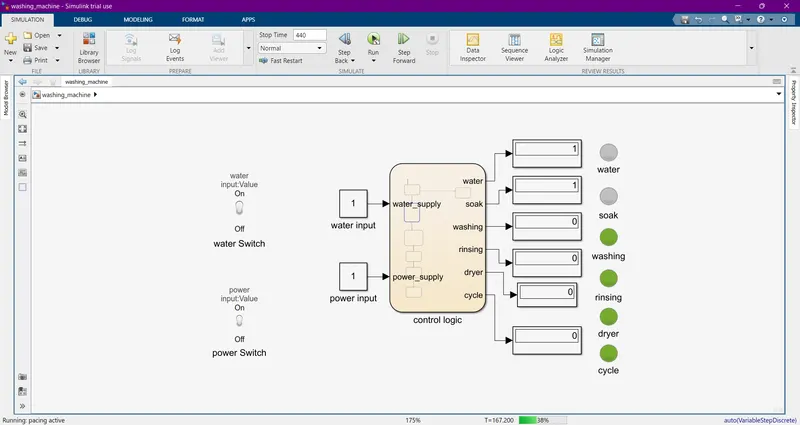
(b) Washing Time:
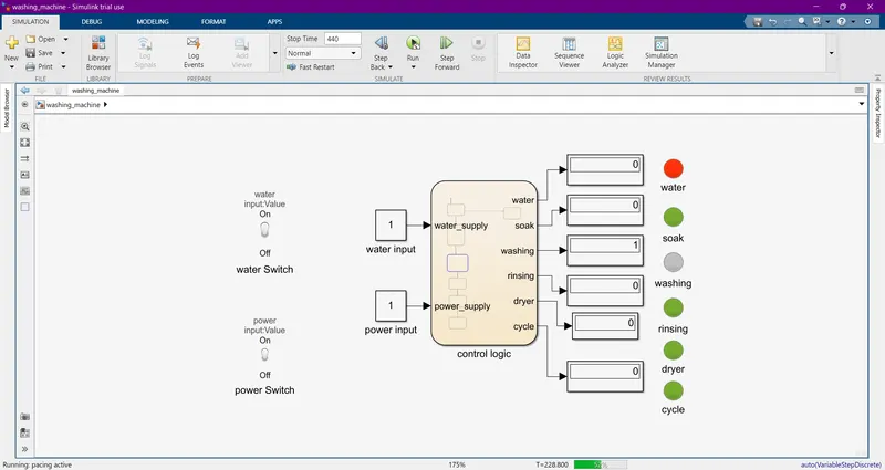
>Here the water supply gets OFF and the washing process runs
(4)The rinsing happens for next 20s & dryer runs for 50s
(a) Rinsing:
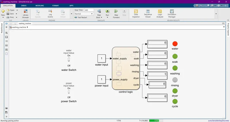
(b) Drying:
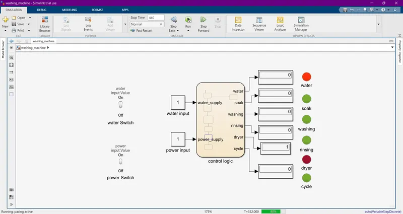
After all the processes have completed turn on the finished LED:
CONCLUSION:
Here all the given conditions are showed seperately at each stage what process is happening...
(2) Make a Simulink chart for the “Gear shift” logic ::
> objective:
Making a simulink chart for the 'gear shfit' for the below mentioned conditions,
Speed Range(kmph) Gear
0 to 15 1
16 to 25 2
26 to 40 3
41 to 60 4
Above 61 5
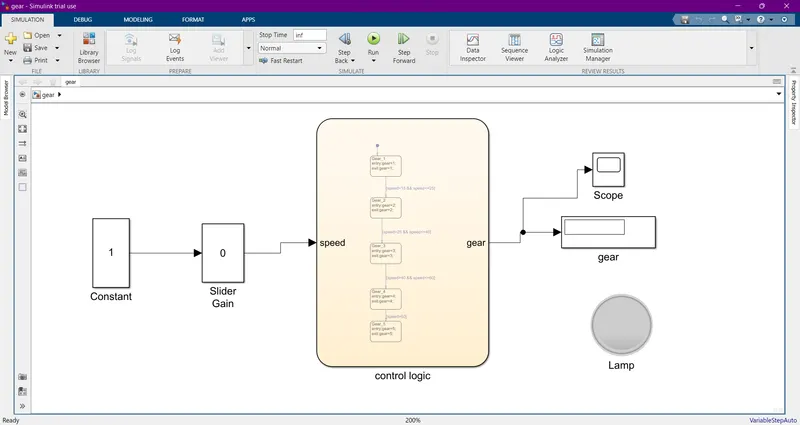
>>BLOCKS Required::
>stateflow: Stateflow is a control logic tool used to model reactive systems via state machines and flow charts within a Simulink model.
>constant: gives an input to the system.
>Display: displays the out put values of the system.
>slider gain: The Slider Gain block performs a scalar gain that you can modify during simulation. Modify the gain using the slider parameter.
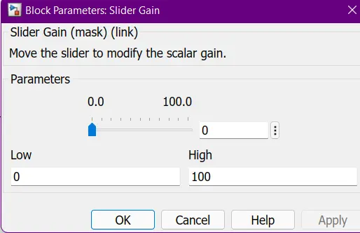
> Here we are changing the speed value from 0 to 100 by using above slider gain block
> Lamp: The Lamp block displays a color that indicates the value of the connected signal.
>> BLOCK DIAGRAM::
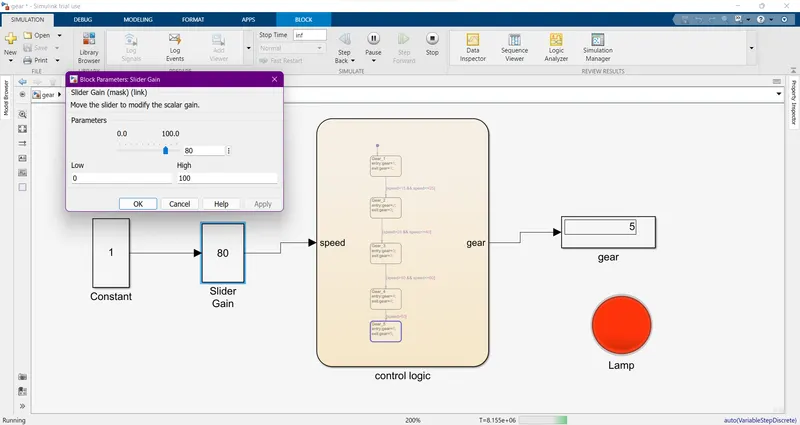
'Gear shift' simulink
>> State flow:
Chart
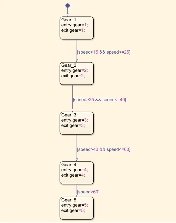
>> CONDITIONS:
>Parameters:
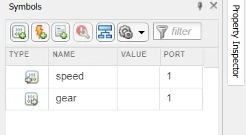
> speed as given as input to the chart
>gear as given as output from the chart
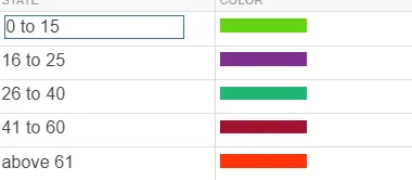
>identification:
speed range(kmph) indication(colour)
>>OUTPUTS:
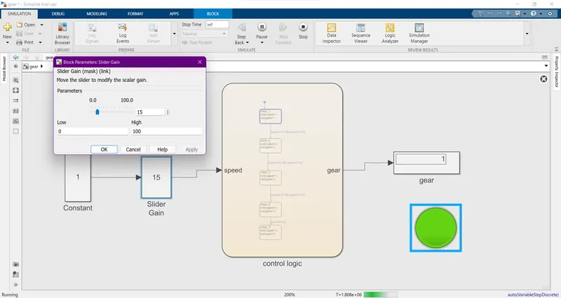
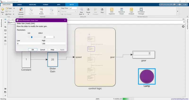
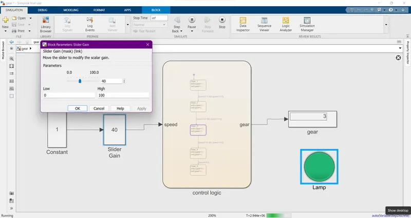
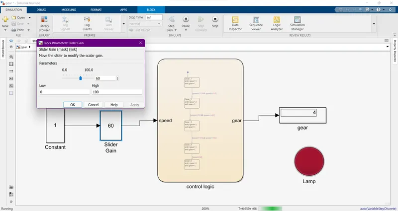
> After giving the all requried connection and inputs then run the simulation by using 'inf' ,then observe the different gears how are trasnmitted.
Gear 1:
Speed range: 0 to 15 kmph
input : 15 kmph
colour: green
>Gear 2
speed range: 16 to 25 kmph
input: 25 kmph
> Gear 3:
speed range: 26 to 40 kmph
input: 40 kmph
> Gear 4:
speed range: 41 to 60 kmph
input: 60 kmph
> Gear 5:
speed : above 61 kmph
input: 80 kmph