Week - 4
AIM: To Implement a control logic for washing machine and Gear shifting of automobiles using Stateflow chart in Simulink.
THEORY:
- Control Logic: Control logic is a vital part of a software program that controls the program's operations. The control logic responds to commands from the user, and it also acts on its own to perform automated tasks that have been structured into the program. Control logic can be modeled using a state diagram, a form of the hierarchical state machine.
- Stateflow: Stateflow provides a graphical language that includes state transition diagrams, flow charts, state transition tables, and truth tables. It is used to describe how MATLAB algorithms and Simulink models react to input signals, events, and time-based conditions. Stateflow enables you to design and develop supervisory control, task scheduling, fault management, communication protocols, user interfaces, and hybrid systems. With Stateflow, you model combinatorial and sequential decision logic that can be simulated as a block within a Simulink model or executed as an object in MATLAB. Graphical animation enables you to analyze and debug your logic while running. Edit-time and run-time checks ensure design consistency and completeness before implementation.
PART-1 CONTROL LOGIC FOR WASHING MACHINE
OBJECTIVE:
Implement control logic of a “washing machine” using Stateflow as per the given sequence:
- If the power supply is available, the system gets activated
- If the Water supply is not available, stop the process & indicate through LED
- Soaking time should be 200s followed by Washing time of 100s.
- Then rinsing happens for the following 20s & dryer runs for 50s.
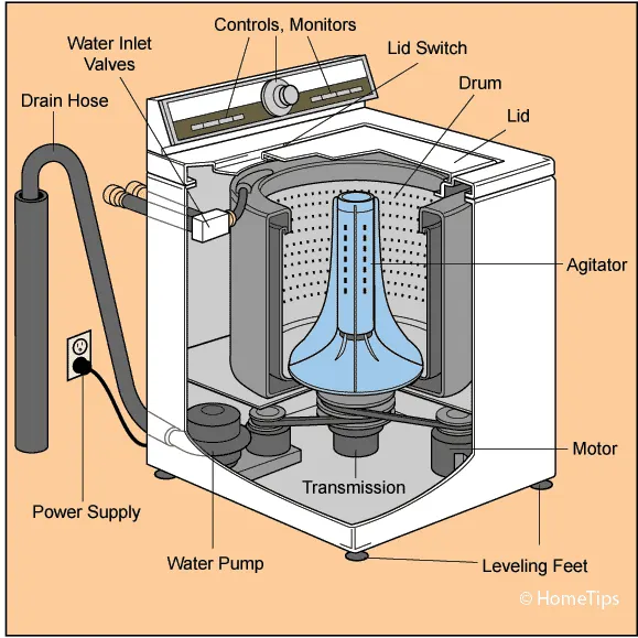
Washing Machine:
- It is a machine capable of handling various tasks like soaking. Washing, rinsing, drying within a short period. All the study performed by the device is based on centrifugation.
- It is a separation process that uses centrifugal force to promote accelerated settling of the particle in the solid or liquid mixture.
- In other words, a washing machine is a machine that washes dirty clothes. It contains a barrel into which the clothes are placed. This barrel is filled with water and then rotates very quickly to make the water remove the dirt from the cloths; these can help make the clothes cleaner.
Input Conditions:
The different states of washing machines
- Soaking-200sec(0-200sec)
- Washing-100sec(200-300sec)
- Rinsing 20sec (300-320sec)
- Drying/Spinning- 50sec(320-370sec)
- Completed/ Stop the machine
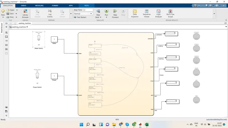
Blocks used in the Simulink model are as under
- Stateflow Chart: Show control logic in the washing machine model.
- Display Block: This block is used for displaying the output result of the given logic.
- Constant Block: This block gives any constant/fixed value as input.
- Toggle switch: The Toggle Switch block toggles the value of the corresponding block parameter between two values during simulation.
- Lamp: Display a color that reflects an input value.
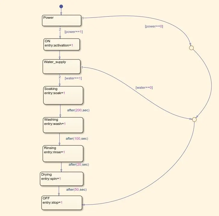
Stateflow logic chart:
Explanation:
- Initially, we have created a power state, and after going through the power state, we have applied one condition [power-=1], which means if power is there, it goes to the second state (ON state).
- If power is not detected, it goes through condition [power-=0] and goes to the OFF state condition.
- As soon as power is detected, the second state(ON state) gets activated and goes to the third state, i.e., Water supply.
- After going through the third state(Water_supply), it goes through water conditions. That means, if [water--1] condition satisfied, then it goes to soaking state for soaking operation for 200 sec. If [water==0] condition was met, it went to OFF mode, where the machine stopped and activated the stop lamp.
- When the soaking operation is done for 200 sec, it gets shifted to the washing state, and washing is done for 100 sec.
- After washing state, it goes to rinsing state for 20 sec where rinsing operation works.
- After the rinsing state is completed, it goes to the drying/spinning state for 50 sec, where the spinning/drying process works for drying the clothes.
- After the drying/spinning state got completed, the machine went to the OFF state, confirming it had followed all the washing steps and washing got completed for clothes, and the machine got stopped.
Simulink Model:
RESULT:
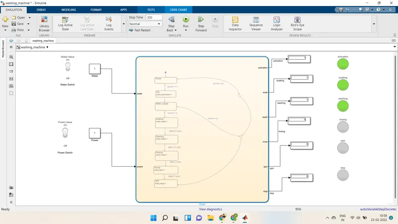
DIFFERENT WORKING CONDITIONS OF WASHING MACHINE:
1. Power supply OFF and Water supply OFF
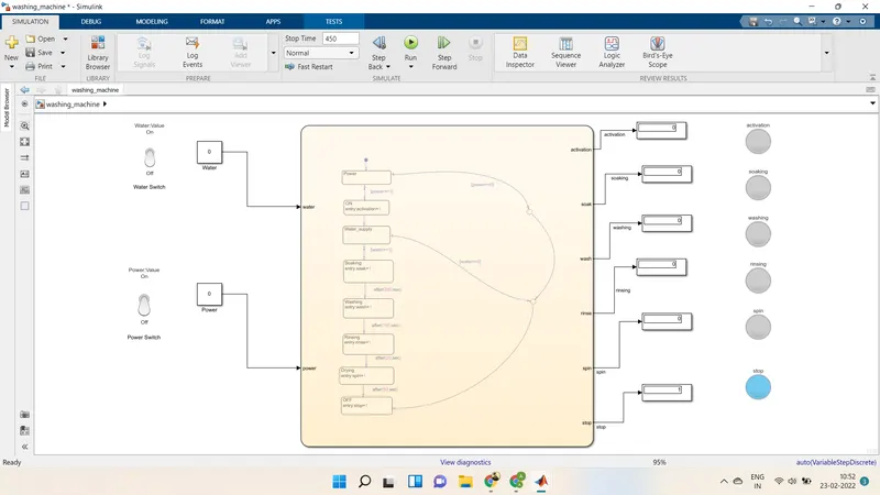
2. Power supply ON and Water supply OFF
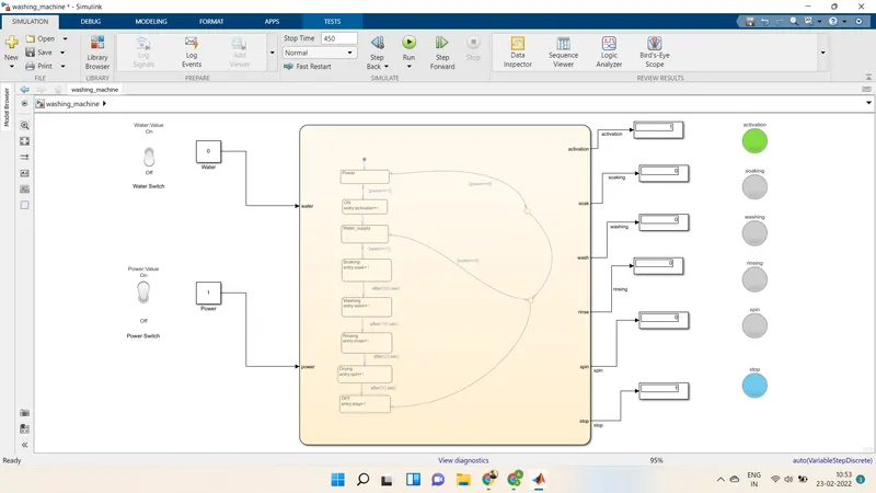
3. Water supply On and Power supply OFF
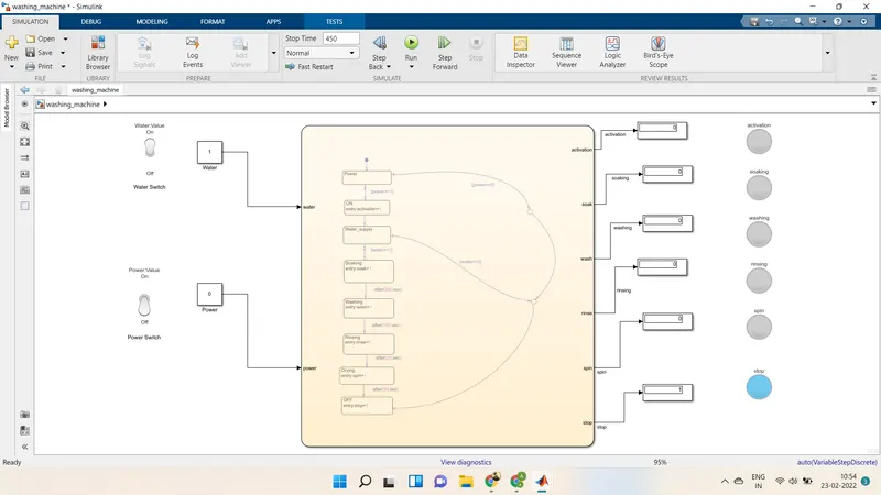
4. Power supply ON and Water supply ON
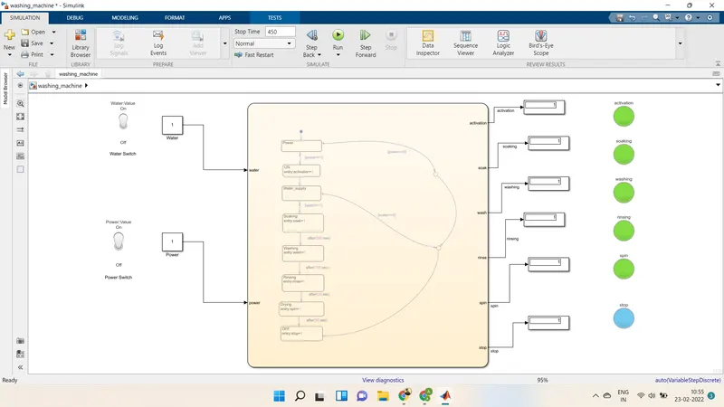
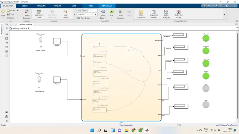
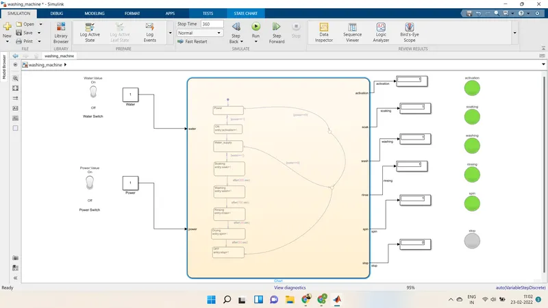
DIFFERENT STAGES OF WASHING MACHINE:
1. Soaking Process
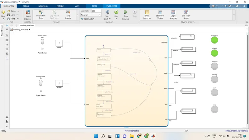
2. Washing Process
3. Rinsing Process
4. Drying Process
CONCLUSION: After performing various calculations, the Simulink model is submitted to give an accurate result. Thus the control logic of the washing machine using the state flow is achieved.
PART-2 SIMULINK CHART FOR THE "GEAR SHIFT" LOGIC
OBJECTIVE:
Make a Simulink chart for the “Gear shift” logic as per the below conditions:
Speed Range(kmph) Gear
0 to 15 1
16 to 25 2
26 to 40 3
41 to 60 4
Above 61 5
Give speed input while the simulation is running & display the gear number.
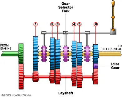
Gear Shift: The gear shifter is responsible for physically engaging the gears on the output shaft, locking them in place so that they turn the shaft and send torque to the drive wheels. As the engine approaches the limits of its RPM band, you shift up to a higher gear ratio to stay within the most effective range.
Input Conditions:
Speed Range(kmph) Gear
0 to 15 1
16 to 25 2
26 to 40 3
41 to 60 4
Above 61 5
BLOCKS USED:
- Slider: The Slider block tunes the value of the corresponding block parameter during simulation.
- Constant Block: Constant/fixed inputs provided to the Stateflow chart.
- Display: We have used the display block to show the vehicle at which gear for a particular speed.
- Real-Time Synchronization Block: This block uses to synchronize model execution to real-time in normal mode.
- Scope: This block is used to visualize the output waveform.
- Custom Gauge: This block indicates the speed given as the input to the state flow and connected to the slider gain so that the value provided will reflect in this custom gauge.
- Vertical Slider Block: This block deflects gear numbers according to the display block's output.
STATE FLOW CHART:
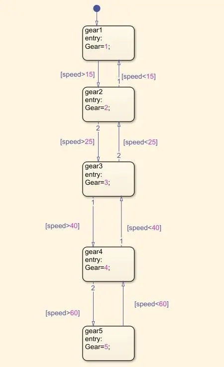
- Initially, we have created the first state(Gear_1), and in this, we have given a condition such that if input speed-15, then the gear got shifted to second gear. That means that if the (speed<-15) requirement is satisfied, the car remains in the first gear only.
- When the (speed-15 condition) satisfied, the car got shifted to second gear(Gear 2 state). Then the vehicle remains in the second gear until the speed goes above 25 units.
- When (speed>25 conditions) got satisfied, then the car shifted to the third state(Gear 3). Further, if the speed rate falls to 25 and below 25 units, the vehicle was again moved to second gear.
- Furthermore, if (speed>40 conditions) got satisfied, then the car shifted to the fourth state(Gear_4). Further, if the speed rate falls to 40 and below 40 units, the vehicle got again shifted to third gear.
- Also, if (speed>60 condition) got satisfied, then the car shifted to the fifth state(Gear 5). Further, if the speed rate falls to 60 and below 60 units, the vehicle got again shifted to fourth gear.
- If the speed remains higher/more significant than 60 units, then the car will stay in fifth gear only until there is any drop-in rate of the vehicle.
SIMULINK MODEL:
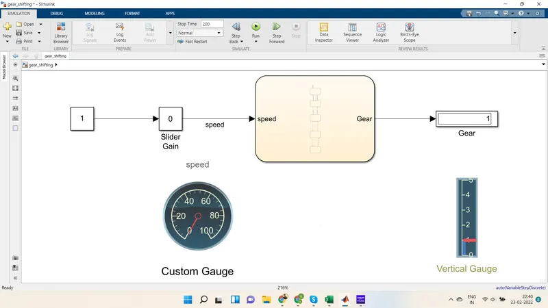
Explanation:
-
Initially, we have taken Slider block to vary our speed input during simulation. Instead of using simulation time as infinite time, we have used real-time kernel block, i.e., Real-Time synchronization.
-
We have connected the slider block to the stable block(speed), and that block is further connected to control logic so that car's gear shifting can be achieved by varying the speed input.
-
Hence, when we increase the speed by moving the slider, then automatically, as per our control logic and given condition, the corresponding gear number was displayed at the output. We have used a display block resulting from the control logic chart to record the gear number for a particular instance of speed.
-
Further, we have also used a vertical gauge block and renamed it as a gear shifting indicator. We have internally connected that Gear shifting indicator block to the display block to deflect the gear number correspondingly.
-
Also, we have used scope block to visualize the output(i.e., Gear number & input, i.e., Speed).
RESULT:
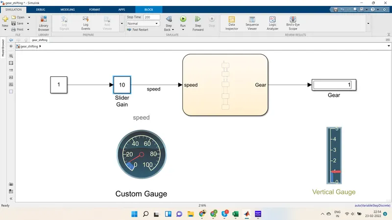
1. For Gear-1
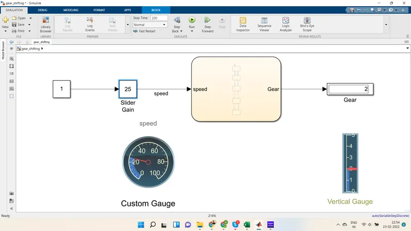
2. For Gear-2
3. For Gear-3
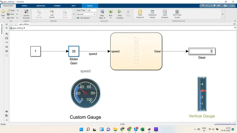
4. For Gear-4
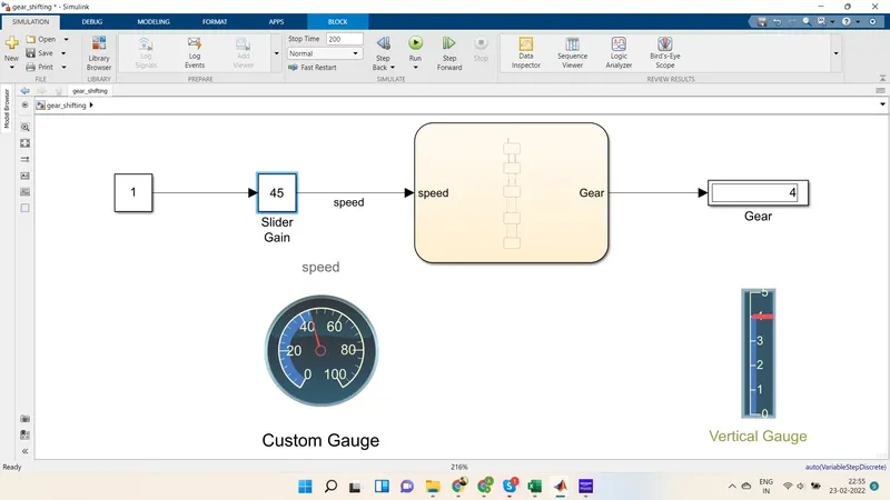
5. For Gear-5
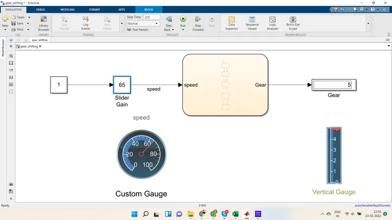
CONCLUSION: Performed various calculations on "Gear Shift," the Simulink model is submitted to give the accurate result. Thus the Simulink chart for the "Gear Shift" logic is made using state flow, and the results are shown.