Week - 4
Objective- Implement control logic of a “washing machine” using Stateflow.
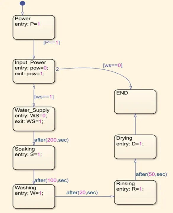
Introduction- In the Matlab using Stateflow the control logic of washing machine is created where the input is power and water supply. When the water and power is available the machine starts operating, after 200 secs the soaking operation takes place and the water supply stops at that moment. When the soaking action (S=1) is completed washing starts (W=1) after 100 secs and after 20 secs of time rinsing action starts at entry point R=1. After 50 secs of rinsing drying process starts at (D=1) and the process ends. When the process gets end the water supply stops (ws==0).
Stateflow Model:-
Simulink Model :-
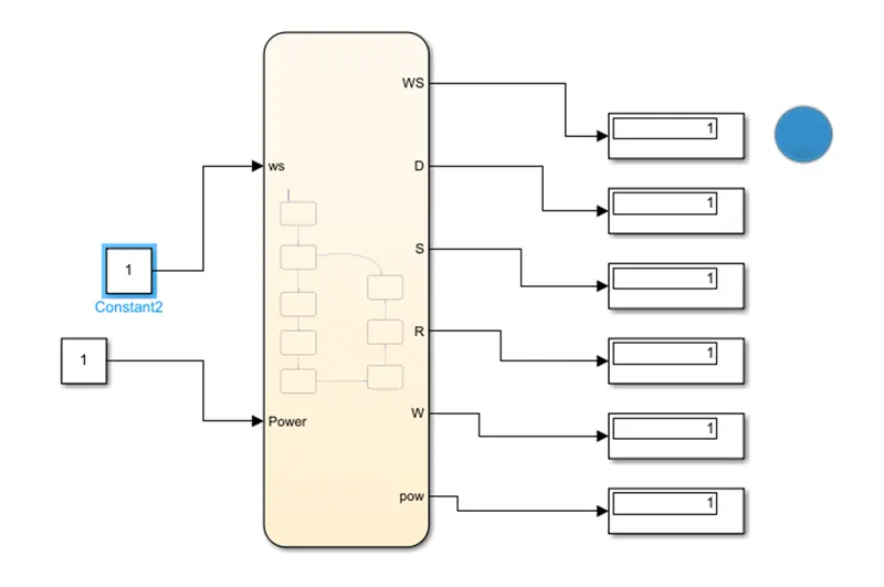
In this stateflow model all the outputs are connected to display in simulink. When the water supply is not available the LED lamp will indicate in colour green and when the water supply is available the lamp will indicate blue in that situation. Also showing entry and exit of water supply as well as the action performed at each step.
Objective- Make a Simulink chart for the “Gear shift” logic and give speed input while the simulation is running & display the gear number.
Introduction- in automatic gear shift system there are certain speed limits which are set according to which at particular speed limit gear should be changed automatically. In this control logic we have set up speed limits of gear 1 to 5 for speed ranging from 0 to 61 and above.
|
Speed Range (kmph) |
Gear |
|
0-15 |
1 |
|
16-25 |
2 |
|
26-40 |
3 |
|
41-60 |
4 |
|
Above 61 |
5 |
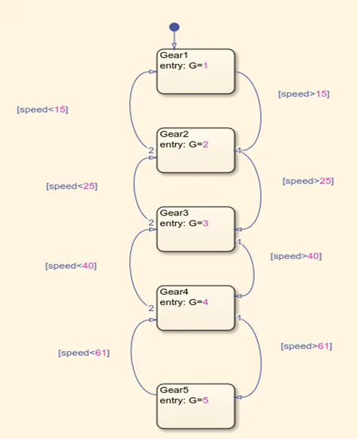
Working :- There are 5 states connected in logic for Gear 1-5. At the speed limit of 0-15 usually the 1st gear operates. As soon as the speed limit exceeds above 15 kmph the first transition takes place and the gear is shifted to G2. In this case the speed between 16-25 kmph the gear remains at G2 as soon as the speed crosses 25 kmph the gear shifts from G2 to G3 and second transition takes place in order to run the vehicle at speed above 26 to 40 kmph. The fourth transition takes place when the speed increases above 40 kmph from one state to gear G4 state automatically. The speed limit for this gear G4 is between 40-60 kmph, here the fifth transition takes place when speed limit exceeds above 60 kmph. The fifth state for G5 will be same for the speed above 61 kmph. In this gear system the gear reduces when the speed range reduced. With reduced speed the gear also changes to lower one with each transition.
Stateflow Model for Gear System
Simulink Model
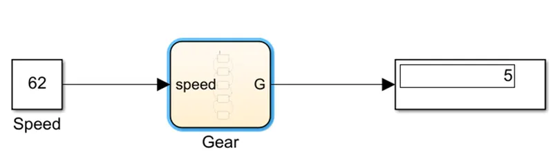
In this Simulink model when we change speed the display shows the gear at which vehicle is running. With every speed change various transition will takes place. For example, in the above model we have considered speed limit at 62, at the speed of 65 the transition takes place in stateflow model for Gear 5 and it is being displayed in the display block. With every speed change we can observe the gear shift.