Project
BAJA Model
CVT Model Dashboard
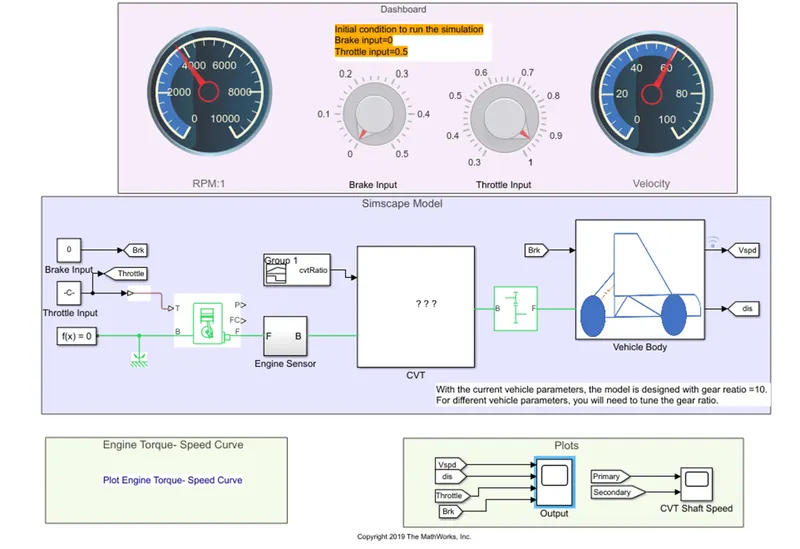
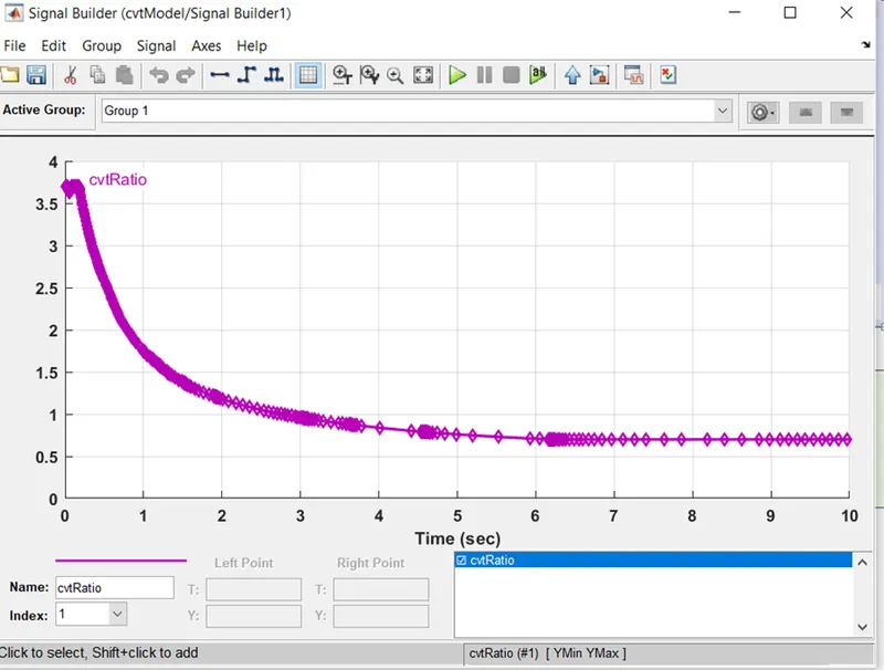
In CVT model we can see that there are various block which are connected in Simscape model where the input blocks for brake input and throttle input are given. As we increase the throttle the power consumption also increases. The input is given to the generic engine block at port T and rotational reference is connected at port B with configuration. The mechanical rotational output is given out by port F of engine sensor and the output is provided through port B to CVT block which is continuous variable transmission which allows the engine to run at constant RPM even if there is change in speed. The CVT ratio is fed into the cvt block through signal builder block. The speed increase and reduction takes place through CVT block where the output is given to the simple gear block from cvt block and the output from simple gear is converted and given to the vehicle body block. Using Grabit the torque speed values are given to the model.
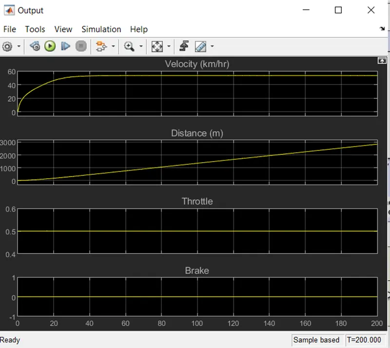
All the results can be observed in the scope for velocity, distance, throttle and brake. The graph is plotted as per the result and also the cvt graph for primary and secondary pulley can be observed in the cvt shaft speed scope block.
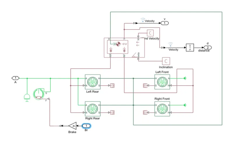
Vehicle block :- in this CVT model inside vehicle block it have modeled the vehicle by taking some realistic parameters and here in vehicle block port H getting feedback from the tires of their motion of front and rear, at the same time input data for head wind speed and inclination angle is given at port W and beta. The output of vehicle body for rear and front tires are given through NR and NF port. Both the front and rear are connected to PS terminator block to terminate physical signals coming from the tires. Hear double shoe brakes are applied to both the rear and front tires.
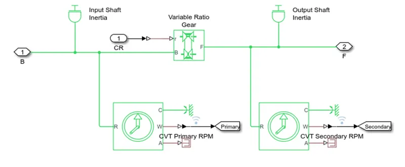
CVT Block :- Continuously Variable Transmission. In this model CVT plays an important role for vehicle as it provides constant RPM while the speed is varying with the change in the gear ratio. It’s a pulley based CVT model where the radius changes with the speed reduction as well as at the time of over speed.
In this CVT block there is one variable ratio gear block connected with input and output shaft inertia and these shafts are connected with ideal rotational sensors at both the ends of input and output of the shaft which are marked as cvt primary and cvt secondary rmp.
Inside CVT Block
CVT Ratio
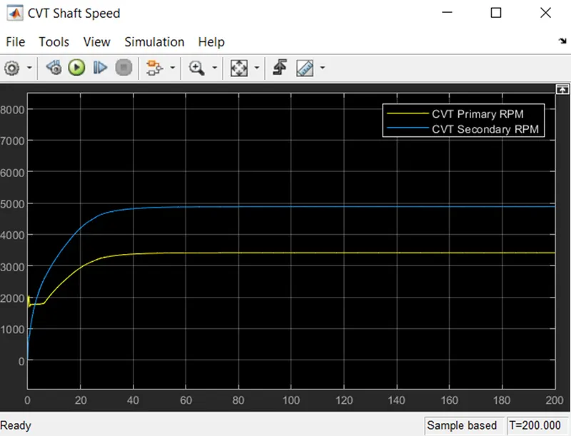
CVT Shaft Speed Results
Here the result for primary and secondary rpm is shown where the radius for pulley changes with change in speed as well as this graph shows that at the time of increase in speed the radius the secondary pully reduces and the primary pulley radius increases. In this way the CVT ratio is maintained.
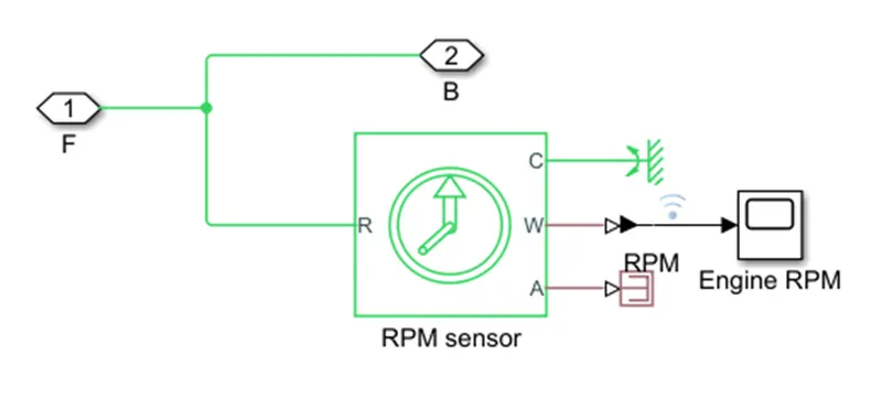
Engine Sensor Block :- In the engine sensor block we have rpm sensor where we get the angular velocity which will define the engine rpm. This engine sensor block is connected with CVT and the generic engine. The port F of generic engine which provides physical output to the engine sensor block and the rpm is given to the CVT block. Here the CVT block will get the physical input sensed through engine sensor block.
Inside Engine Sensor Block
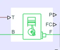
Generic Engine Block:- throttle is provided to the engine from signal builder block through which is required to produce a torque required to start the engine. Once the engine gets start the rotational mechanical force is created and that force is given to the engine sensor block through port F which stands for output mechanical rotational conserving port. The port B is connected to mechanical rotational reference with solver block. The mechanical rotational force will be positive if that force is greater than the force at port B.
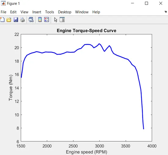
By using Grabit the torque speed curve has been plotted and given to the input. Through Grabit we can extract the data from any image and extract the points. Here in this system model, we have used Torque Speed Curve.
Results :- In the scope we can see the results at 200 secs stop time. Velocity, Distance, Throttle and Brakes graph is shown. From here it is clearly noticed that at the increase in velocity from 0 to 55 at which the distance travelled around 3 kms. The throttle at constant torque without applying brakes. From these results we can understand that at constant torque is necessary to maintain the speed for particular distance (3km) to be covered.