Week -2
Door Bell Using Solenoid Block Model
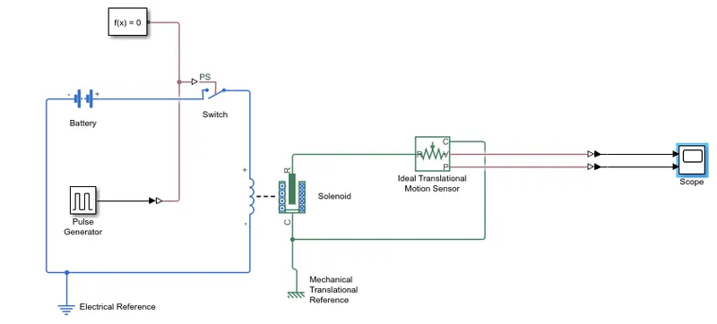
The model represents operations of doorbell in which solenoid switch is operating with electrical and mechanical characteristics operating with DC voltage source. Port R moves towards Port C when operating and providing mechanical reference to port C.
Switch with external physical signal is used for providing signals using pulse generator. The switch is connected with battery and also connected in series with Solenoid switch provided with electrical reference. Ideal Translational Motion Sensor is used to sense the position of the plunger. In output we can measure the velocity and the position of the plunger and result can be seen in scope.
When the pulse generator gives signal, the electrical switch becomes ON and the electric circuit operates and solenoid switch operates and Port R move towards C and switch becomes close path. Ideal sensor senses the position and operation of solenoid.
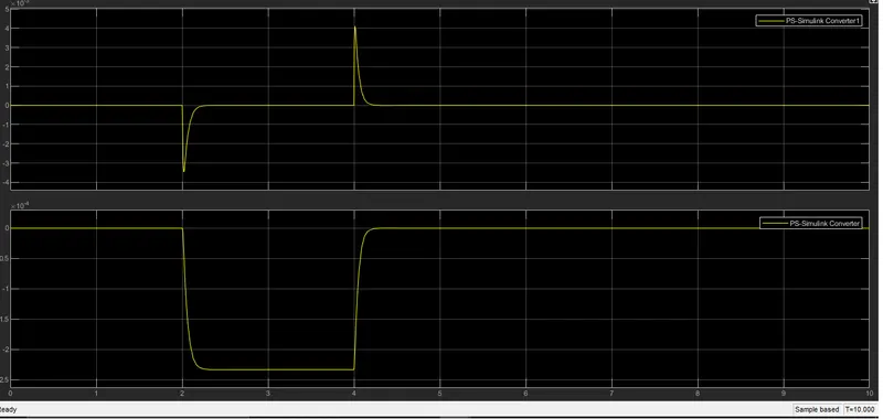
These are the result obtained with the first graph showing velocity and second graph shows the position of the plunger. At first instance when the pulse generator gives positive signal at that time switch is closed the plunger comes down and the port R comes close to Port C which we can see in second graph which shows the position after 2 sec bell starts ringing and as soon as the pulse generator signal gives another pulse with that the switch opens and the plunger moves away from the port C at that time bell stops ringing. The pulse is given at 20% of the pulse width to obtain the delay.
Thermistor Operated Fan Model
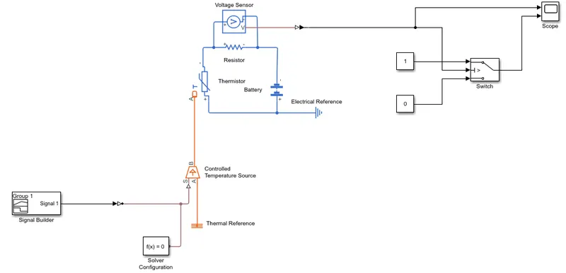
Block diagram represents a thermistor model operating fan. Here thermistor is provided with thermal source with changing heat input signal using signal block giving heating input signal for particular time period.
In this model controlled temperature source output is connected with thermistor with one port connected to thermal reference and other with physical signal with solver configuration. Here signal builder block in which variable signal is provided for 20 degree C from 0-10 sec, 27 degree C from 10-30 sec and 25 degree C from 30-50 sec. Using Simulink to PS converter these signals are converted and given to S port of controlled temperature source block. Port B of CTS block connected to thermistor input port A. Thermistor is connected with resistor, whenever the temperature of thermistor increases the value of resistance also changes with change in temperature. Here electric circuit of this model is connected with resistor and battery source provided with electrical reference.
For operation of fan we have connected one switch provided with input 0 and 1 for showing on and off. Voltage source is connected in parallel across resistor to and output is connected to scope and output of switch is also connected to scope to check the exact time of on position of switch when temperature is above 25-degree C.
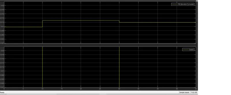
According to the condition the fan should get on when temperature rise above 25 degree C for that threshold value of switch is set to 0.012V (threshold value at 25 degree C is 0.012V). The result can be seen in scope block for both voltage output and switching position.
In result we can see that for temperature at 20 degree C for 0-10 sec voltage value is at 0.009 V, for 10-30 secs at 27 degree C the voltage value is at 0.012 V at this moment of time we can observe that fan turns on as the threshold value is crossed and at 30-50 sec at 25 degree C the fan turns off as the threshold value comes down to 0.012.