Week - 4
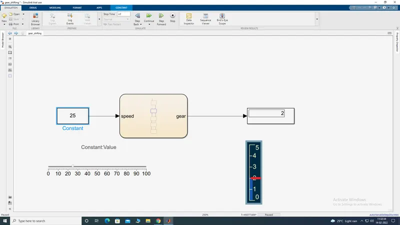
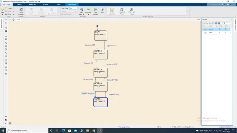
Make a Simulink chart for the “Gear shift” logic as per below conditions:
Speed Range(kmph) Gear
0 to 15 1
16 to 25 2
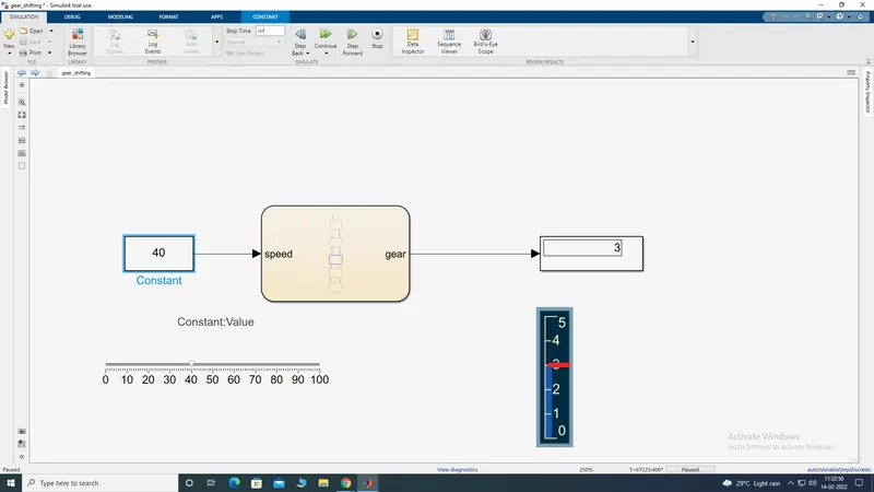
26 to 40 3
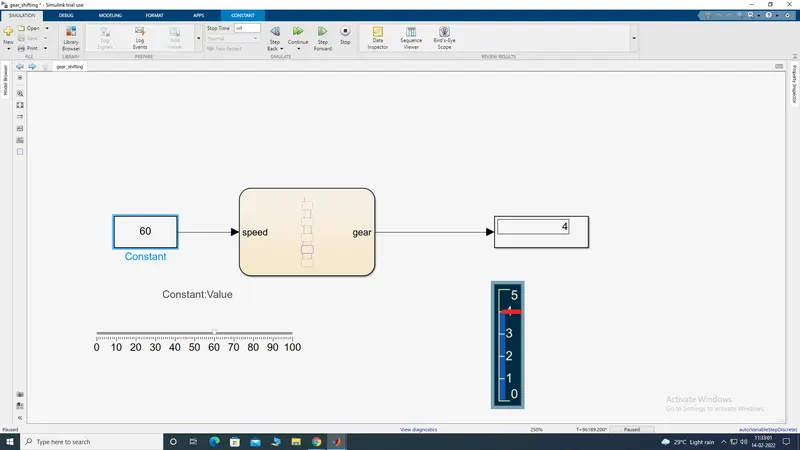
41 to 60 4
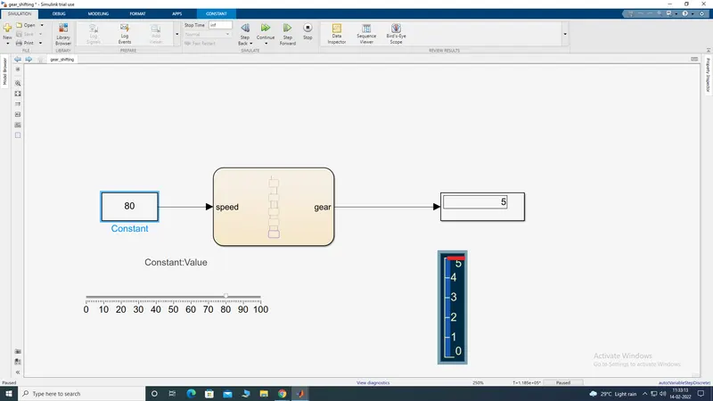
Above 61 5
THEORY:
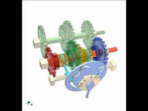
GEAR SHIFTING:
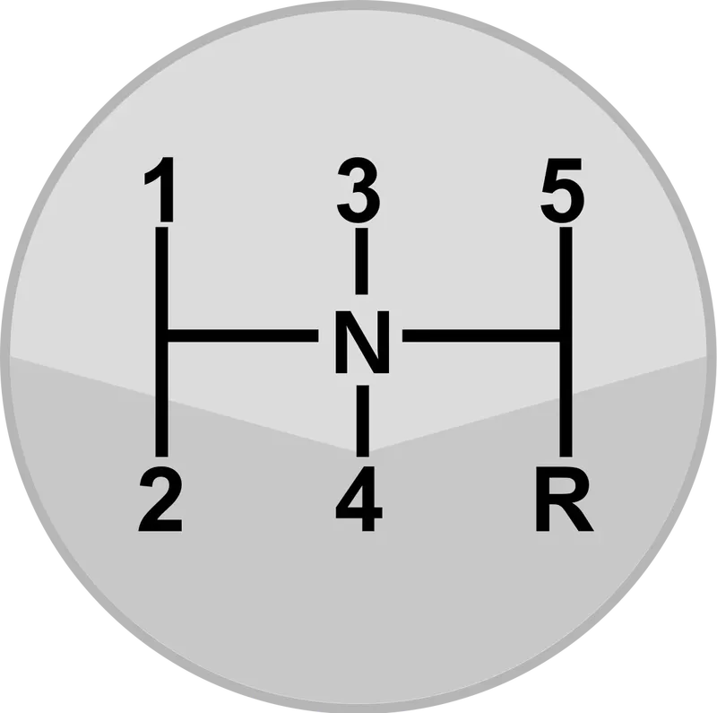
GEARS DEFINITION:
The basic rule is that you change up through the gears as the speed of the car increases and down when you need more power from the engine. ... First gear provides the most pulling power but the least potential for speed, whilst fifth gear which provides the least pulling power allows the greatest range of speed.
SIMLINLK DIAGRAM:
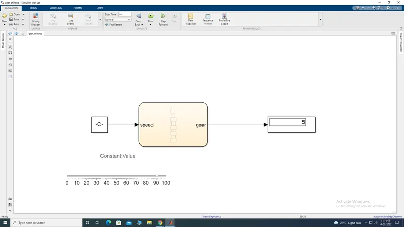
Blocks used in the Gear-shifting model :-
- Slider :- The Slider block tunes the value of the connected block parameter during simulation.
- Constant Block :- Constant/fixed inputs provided to the stateflow chart.
- Display :- We have used the display block to show the vehicle is going at which gear for particular speed
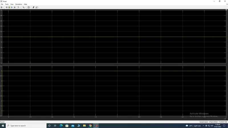
- Scope :- This block is used to visualize output waveform.
- Vertical Slider Block :- This block is used so that it can deflect gear number according to the display block's output.
GEAR CHANGING STEP BY STEP:
FIRST GEAR:
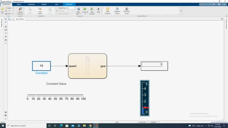
SECOND GEAR
THIRD GEAR:
FOURTH GEAR:
FIFTH GEAR:
STATE FLOW CHART:
OUTPUT GRAPH:
PART=B
- Implement control logic of a “washing machine” using Stateflow as per given sequence:
- If the power supply is available, the system gets activated
- If the Water supply is not available, stop the process & indicate through LED
- Soaking time should be 200s followed by Washing time of 100s.
- Then rinsing happens for next 20s & dryer runs for 50s
WASHING MACHINE:
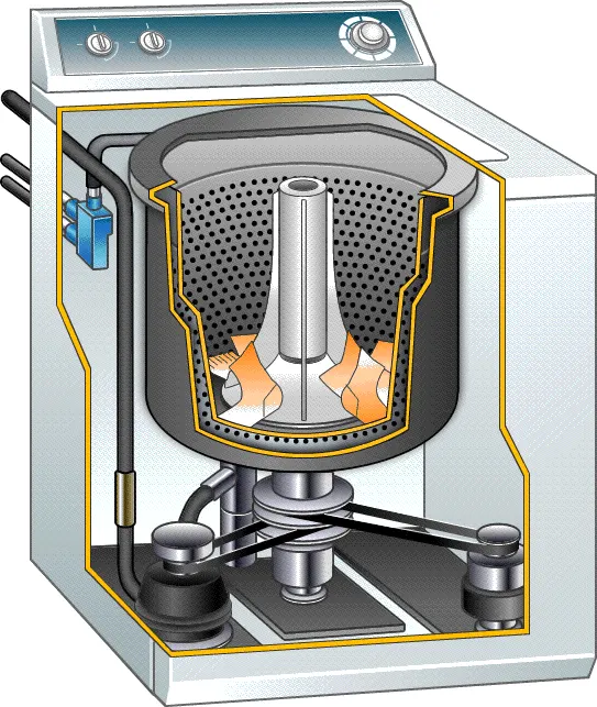
- It is a machine which is capable of handling various tasks like soaking, washing, rinsing, drying within a short period of time. all the task performed by machine is based on the centrifugation.
- It is a separation process that used centrifugal force to promote accelerated settling of the particle in the solid or liquid mixture.
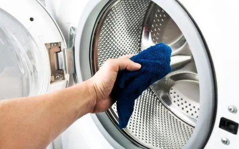
- In other words, a washing machine is a machine that washes dirty clothes.it contains a barrel into which the clothes are placed. this barrel is filled with water and then rotates very quickly to make the water remove the dirt from the cloths. these can help make the clothes cleaner.
The different states of washing machines
- Soaking- 200sec(0-200sec)
- Washing- 100sec(200-300sec)
- Rinsing- 20sec(300-320sec)
- Drying/Spinning- 50sec(320-370sec)
- Completed/ Stop the machine..
state flow logic diagarm:
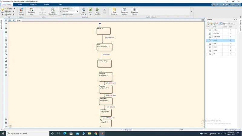
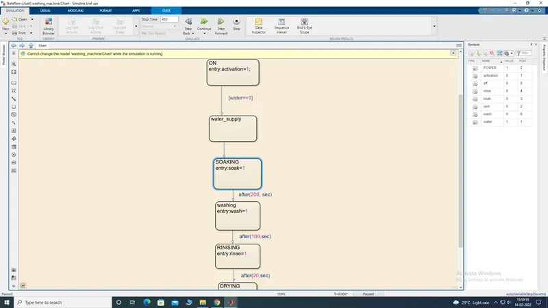
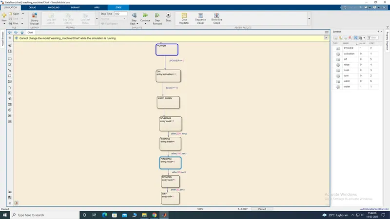
IN STATE FLOW HERE FROM THE 1 CHART AM USING POWER CHART THE GIVEN THE INPUT
2.ON CHART FOR THE USING THE OUT PUT
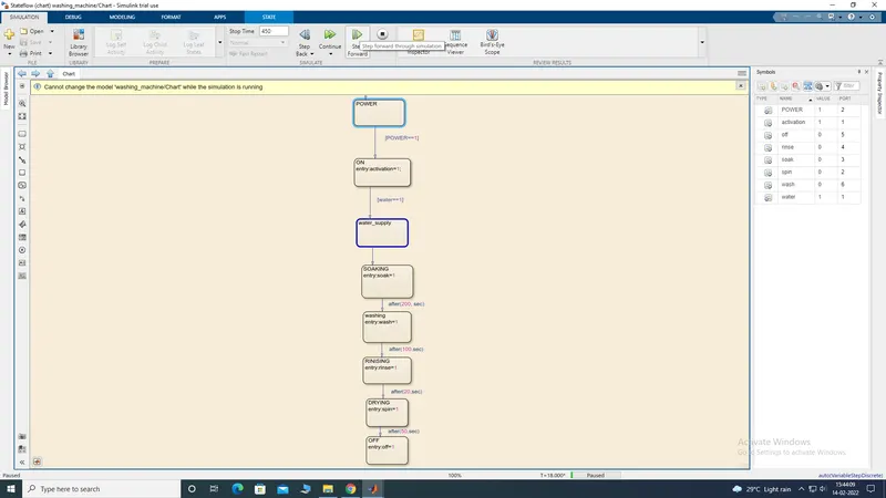
3.WATER SUPPLY IS THE INPUT OF CHART
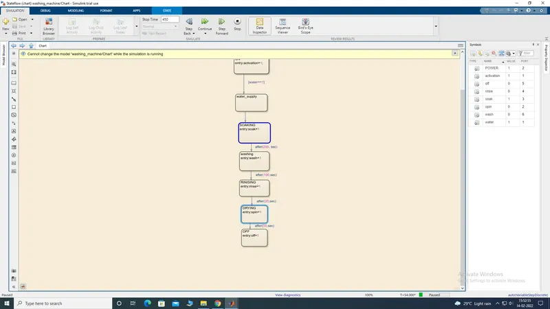
4.SOAKING CHART IS USING THE OUTPUT WE GIVE THE TIME 200 SEC TO THE AFTER SOAKING WATER GET INSIDE
5.WASHING IS THE OUTPUT CHART WE GIVE THE TIME 100 DEC AFTER WASHING
6.RINSING IS THE OUT PUT CHART WE GIVE THE 300 - 320 SEC AFTER RINSING
7.DRYING IS THE OUTOUT CHART WE GIVE THE TIME 50 SEC AFTER THE DRYING
8.FINALLY WE GIVE THE OFF TO THE CHART FINISHING THE PROCESS OFF CONDITION WHEN THE MEACHINE GET RUNNING CONDITION
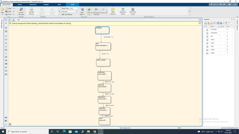
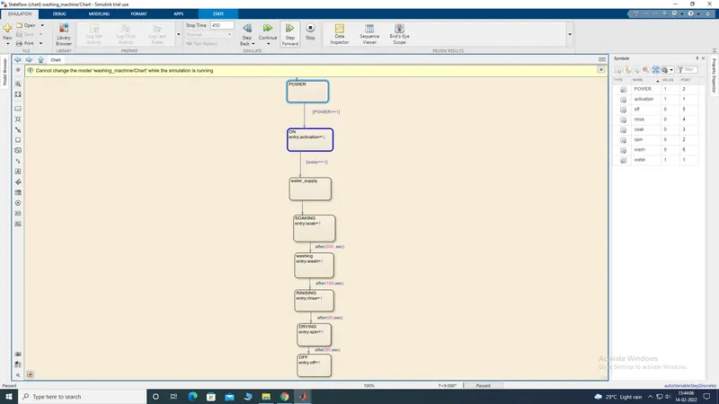
HERE THE STEP BY STEP PROCESS:
STEP 1:
POWER TO ACTIVATION:
STEP2:
STEP:3
STEP 4
STEP 5
STEP 6:
STEP 7 :
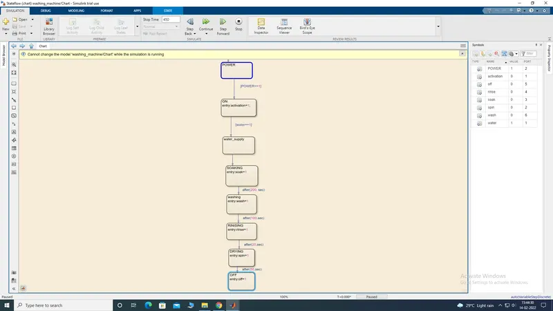
DIAGRAM:
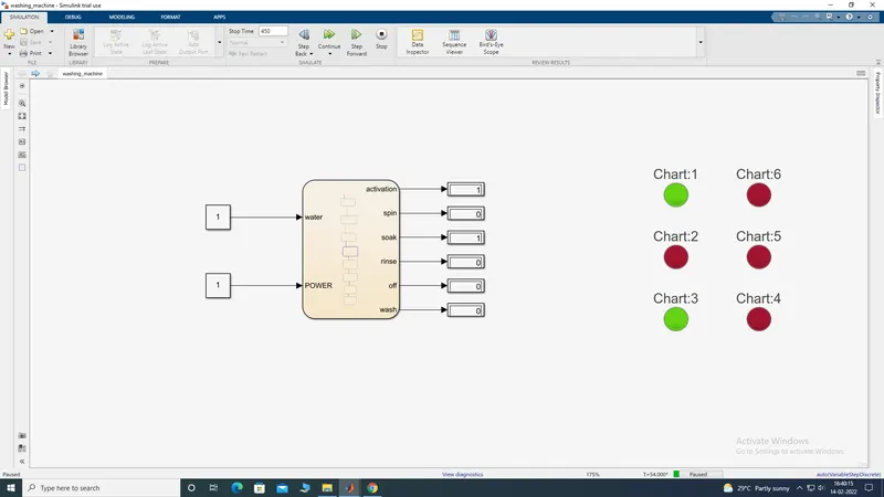
HERE THE OUTPUT BLOCKS:
WE USED THE BLOCKS
1.CONSTANT
2.DISPLAY
3.LAMP
CONSTANT BLOCK USES TO GIVE THE INPUT VALUES TO THE BLOCK:
DISPLAY: BLOCK IS USED TO THE GIVE THE OUTPUT VALUES
LAMP:BLOCK IS USED TO INDICATES THE LIGHT SIGNAL WHEN WE CONNECTS THE SIHNAL TO INPUT...
0-FOR THE RED LIGHT..
1-FOR GREEN LIGHT..