Project 1 (Mini Project on Vehicle Direction Detection
MINI-PROJECT:
General Overview:
Identifying the direction of the vehicle is one of the important & diverse features in Autonomous driving & Advanced Driver Assistance Features. This particular sub-feature of identifying the direction of vehicle is basically identifying the direction the vehicle is taking based on the camera input.
Camera reads the road signs & stores into its memory with unique values for left turn, right turn & straight drive. Depending on the direction it is taking, final indication is given to the driver – as an indication if he is driving in the recommended direction or not.
Vehicle Direction Determination can also be coupled along - side features like GPS systems to identify whether the vehicle is reaching its destination in an optimized manner. This sub feature can also be used along with Lane Detection, Highway Warning, Ramp Entry / Exit in Wrong Way Detection etc.
STEERING WHEEL DTETECTION SYSTEM:
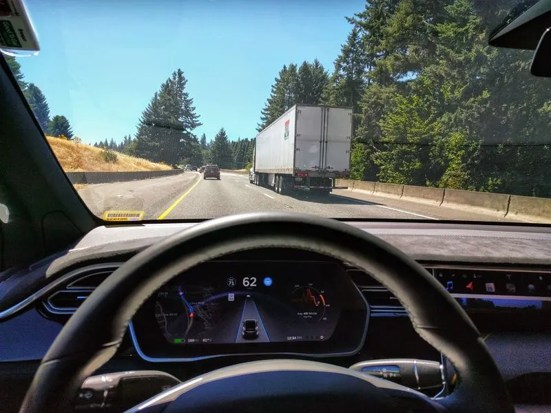
Advanced driver assistance systems (ADAS) are systems which help the driver in the
driving process. The system increases car and road safety when designed with an appropriate human-machine interface. Automated driving (AD) is the ultimate automation level where the human driver is relaxed from his primary task. Regulation evolution is required for providing a common and safe technical framework for the
development of these systems...
CAMERA DETECTION SYSTEM:
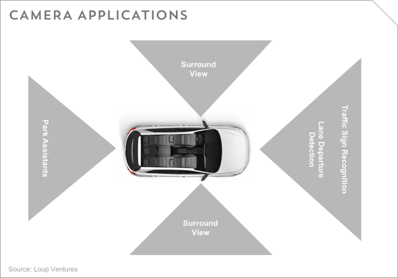
STEP 1:
we have to create the blank model in sumlink to subsystem:
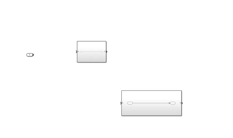
step 2:
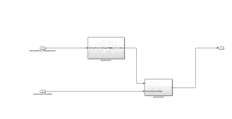
in this we have to create two subsytem one for camera and another for steering wheel detection:
Requirement - 1:
- Steering wheel input as yaw rate (Signal name: SteeringWheel_YawDegreeInput) is the input for this system.
- This is compared against 3 angular values, one each for left turn, right turn & straight drive (Calibration Values: Right_Turn_AngularLimit, Left_Turn_AngularLimit, Straight_Drive_Steering_Angle) to say which specific direction the steering wheel is turning towards.
- Use switch blocks to compare & develop this requirement. Keep this requirement in a subsystem & output of this requirement is a local signal (Signal Name: Vehicle_Turn_Status).
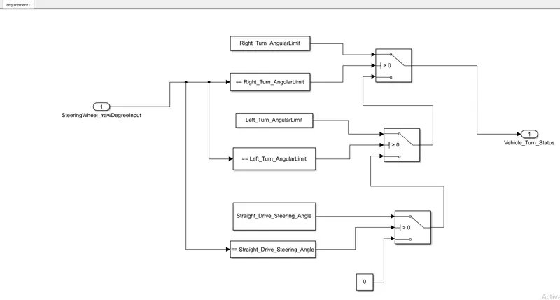
EXPLANATION:
ON THE STEERING WHEEL_YAW DEGREE INPUT:
1.RIGHT_TURN_ANGULAR_LIMIT:
2.LEFT_TURN_ANGULAR_LIMIT:
3.STRIGHT_DRIVE_STEERING_ANGLE
RIGHT_TURN_ANGULAR_LIMIT=WE HAVE THE CONDITION TO THE RIGHT TURN THE STEERING ANGULAR LIMIT.ITS SHOULD EQUAL TO THE CONDITION:
LEFT_TURN_ANGULAR_LIMIT= WE HAVE THE CONDITION TO THE LEFT SIDE THE STEEERING ANGULAR LIMITS ITS SHOULD GIVE THE INDICATION THROUNGH THE CORRECT WAY OF THE LEFT ANGULAR SIDE....
STARIGHT_DRIVE STEERING= WE THE CONDITION FUNCTION THE VECHICLE INTO THE STRAIGHT LINE SHOULD BE INDICATES THE VECHICLE GO THROUGH THE STRIGHT WAY ON THE LANE PATH..
Requirement – 2:
- Keep this requirement as a separate subsystem. Inputs to this requirement are local signal from requirement 1 (Signal Name: Vehicle_Turn_Status) & an input signal from camera (Signal Name: CameraInput_RoadSign), which confirms the occurrence of a road sign.
- Signal Vehicle_Turn_Status is compared against calibration values (Calibration Values: RightTurn_RoadSign, LeftTurn_RoadSign, Straight_RoadSign), if each of them is found equal, then each of the three corresponding output is compared against the camera input signal,
- Using a logical operator block, only one among them is finally given as output signal (Signal Name: Vehicle_Direction_Indicator.....
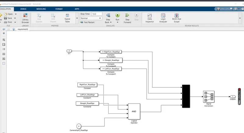
CAMERA INPUT SIGN:
THE CAMERA IS USED THE DETECTION THE OUTSIDE OBJECT..THE RADOR IS USED TO OBSERVE THE FUNCTIONS IN OUTSIDE IT SHOULD BE GIVE THE INPUT THROUGH THE STEERING WHEEL...
RIGHT_TURN_ROAD SIGN
LEFT_TURN_ROAD_SIGN
STRIGHT_RAOD_SIGN
RIGHT TURN RAOD SIDE WE HAVE TO FUNCTION THE CONDITION THE CAMERA SHOULD BE GIVE THE INSTRUCTION THROUGH THE STEERING WHEEL
LEFT SIDE ROAD SIGN WE HAVE TO FUNCTION THE CONDITION THE CAMERA SHOULD BE GIVE THE INSTRUCTUION THROUGH THE LEFT SIDE FUNCTION AREA
STRIGHT ROAD SIGN WE GAVE THE FUNCTION THE CAMERA SHOULD BE FUNCTION THE DETUCTION THE PATH TO THE STRAIGHT WAY...
SLDD FILE FOR GIVE THE INPUTS FOR THE BLOCKS:
Signals & Calibration Data List:
Step 2 :-
Create a new data directory in the given folder and named it by giving .sldd extension.
|
Signal / Calibration Name |
Signal Type |
Data Type |
Dimension |
Min |
Max |
Initial Value |
Units |
|
SteeringWheel_YawDegreeInput |
Input |
Int16 |
1 |
-180 |
180 |
- |
Deg |
|
CameraInput_RoadSign |
Input |
Boolean |
1 |
0 |
1 |
- |
- |
|
Vehicle_Turn_Status |
Local |
Int16 |
1 |
-180 |
180 |
- |
Deg |
|
Right_Turn_AngularLimit |
Calibration |
Int16 |
[1 1] |
-180 |
180 |
30 |
Deg |
|
Left_Turn_AngularLimit |
Calibration |
Int16 |
[1 1] |
-180 |
180 |
-120 |
Deg |
|
Straight_Drive_Steering_Angle |
Calibration |
Int16 |
[1 1] |
-180 |
180 |
0 |
Deg |
|
RightTurn_RoadSign |
Calibration |
Int16 |
[1 1] |
-180 |
180 |
30 |
|
|
LeftTurn_RoadSign |
Calibration |
Int16 |
[1 1] |
-180 |
180 |
-120 |
|
|
Straight_RoadSign |
Calibration |
Int16 |
[1 1] |
-180 |
180 |
0 |
|
|
Vehicle_Direction_Indicator |
Output |
Boolean |
1 |
0 |
1 |
- |
- |
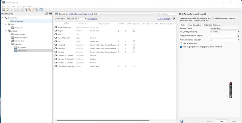
SLDD FILE FOR DESING DATA:
Tagging for requirement:
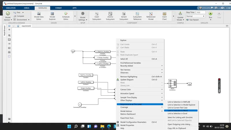
We have considered above steps while tagging the Requirement1 and Requirement2 and the same are as under;
Tagging for Requirement1 :-
steering wheel input as yaw rate (signal name as per the input)
THIS is the compared to the 3 angular values one each for left turn and stright drive
use this switch block to compare and develop the reqirements keep this reqirements keep the requirement in a subsystem subsystem in output of this requirmrnt:
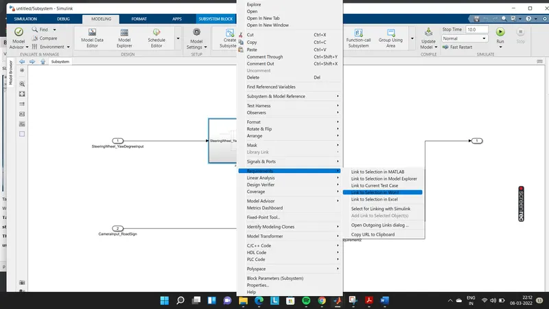
TAGGING FOR REQUIREMENT2:
KEEP THIS REQIUREMENT TO THE SUBSYSTEM INPUT TO THIS REQUIRMENT ARE LOCAL SIGNAL REQUIEEMENT WHICH COMAPRES THE OCCURS THE COMPARE THE SINGS:
Conclusion :-
We have sucessfully model the Vehilcle Direction Determination and also . Further, we also used tagging the subystems and creation of SLDD file...