Week -2
1.BLOCK DAIGRAM:
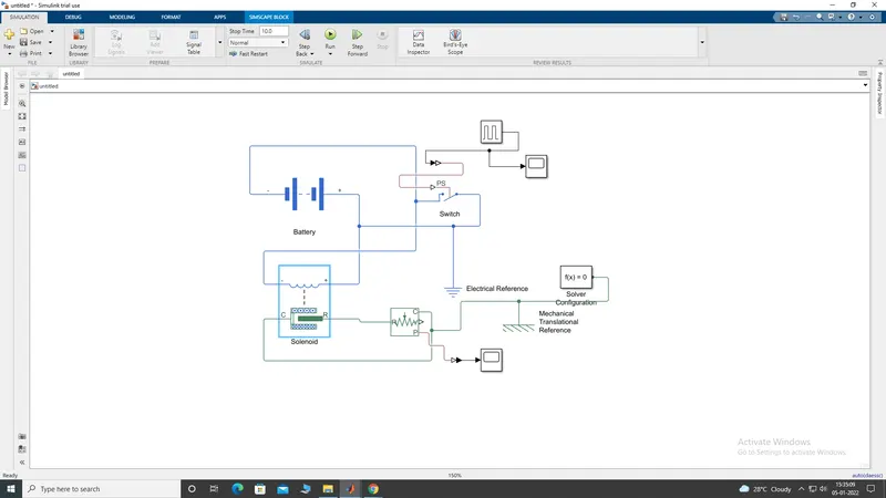
GRAPH
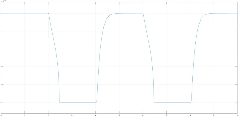
HERE THE EXPALNATION;
SOLENIOD
This block implements the electrical and mechanical characteristics of a solenoid.THIS ONE IS CONNECTED TO THE POSTIVE TERMINAL OF THE BATTERY..THE CONNECTION THROUGH PARALLEL SERIES
BATTERY;
This block models a battery. If you select Infinite for the Battery charge capacity parameter, the block models the battery as a series internal resistance and a constant voltage source
SWITCH;
The block represents a switch controlled by an external physical signal. If the external physical signal PS is greater than the threshold, then the switch is closed, otherwise the switch is open
pulse-generator:
Time-based is recommended for use with a variable step solver, while Sample-based is recommended for use with a fixed step solver or within a discrete portion of a model using a variable step solver.
IDEAL TRANSITIONAL MOTION SENSOR:
This block measures velocity or displacement in a mechanical translational network. The sensor is ideal since it does not account for inertia, friction, delays, energy consumption, and so on.
ELECTRICAL REFERANCE
Electrical reference port. A model must contain at least one electrical reference port (electrical ground).
MECHANICAL REFERENCE;
This block represents a mechanical translational reference point, that is, a frame or a ground. Use it to connect mechanical translational ports that are rigidly affixed to the frame (ground).
SOLVER BLOCK
Defines solver settings to use for simulation.
2.Use a thermistor to sense the temperature of a heater & turn on or turn off the fan as per below conditions:
Temperature source: 20 °C from 0 to 10 seconds, 27 °C from 10 to 30 seconds, 23 °C from 30 to 50 seconds
Fan conditions: ON if the temperature above 25 °C, OFF otherwise
SOLUTION :-
Theory :-
Thermistor :-
-
A thermistor was first discovered by Michael Faraday in 1833 on a silver sulfide which showed a behavior of decrease in resistance when temperature increased.
-
A thermistor is a semiconductor that has a resistance capacity more than a conducting material and less than insulating material. Its electrical resistance varies with the change in the temperature or thermally sensitive resistor. There are mainly two types of thermistors, namely the Negative Temperature Coefficient (NTC) and the Positive Temperature Coefficient (PTC).
-
Thermistor’s relation with temperature also depends on the material in which it is made. A negative temperature coefficient (NTC) thermistor will decrease its resistance value when temperature increases whereas a Positive temperature coefficient (PTC) will increase its resistance when temperature increases.
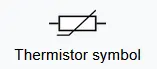
- The electronic symbol of the thermistor is given below;
- NTC thermistors are widely used in industries for different applications like temperature measurements, temperature control, and different applications NTC is an integral part of. PTC is mostly seen in circuit protection, current-limiting resistors.
- Thermistors have high sensitivity which can be up to 10 percent change per degree celsius and their typical response time is 0.5 to 5s with an operating range from -50 to ~300 °C and there are devices with more capacity.
Circuit Diagram :-
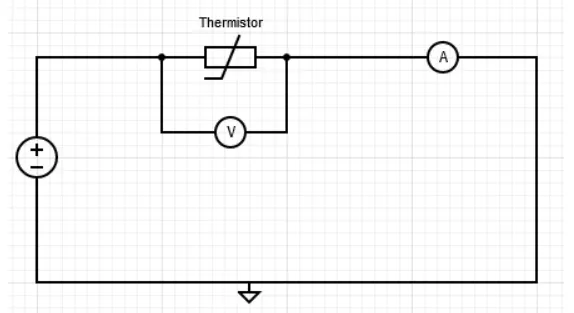
Different Types of Blocks used in Simulink model are as under;
1) Thermistor Block :-
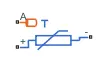
- The Thermistor block represents an NTC thermistor using the B-parameter equation. The resistance at temperature T is
R=R0exp(B(1/T−1/T0))
where:
-
R0 is the nominal resistance at the reference temperature T0.
-
B is the characteristic temperature constant.
The following equation describes the thermal behavior of the block:
Q=Kd*tc*dT/dt
where:
-
Q is the net heat flow into port A.
-
Kd is the Dissipation factor parameter value.
-
tc is the Thermal time constant parameter value.
-
dT/dt is the rate of change of the temperature.
2) Signal Builder :-
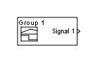
- The Signal Builder block allows you to create interchangeable groups of piecewise linear signal sources and use them in a model. You can quickly switch the signal groups into and out of a model to facilitate testing. In the Signal Builder window, create signals and define the output waveforms.
3) Switch :-

- The Switch block passes through the first input or the third input signal based on the value of the second input. The first and third inputs are data input. The second input is a control input. Specify the condition under which the block passes the first input by using the Criteria for passing first input and Threshold parameters.
-
Pass through input 1 when input 2 satisfies the selected criterion; otherwise, pass through input 3. The inputs are numbered top to bottom (or left to right).
-
The first and third input ports are data ports, and the second input port is the control port. The criteria for control port 2 are u2 >= Threshold, u2 > Threshold or u2 ~= 0.
4) Battery :-

-
This block models a battery. If you select Infinite for the Battery charge capacity parameter, the block models the battery as a series internal resistance and a constant voltage source. If you select Finite for the Battery charge capacity parameter, the block models the battery as a series internal resistance plus a charge-dependent voltage source defined by:
V = Vnom*SOC/(1-beta*(1-SOC))
where SOC is the state of charge and Vnom is the nominal voltage. Coefficient beta is calculated to satisfy a user-defined data point [AH1,V1].
5) Voltage Sensor :-
- The block represents an ideal voltage sensor, that is, a device that converts voltage measured between any electrical connections into a physical signal proportional to the voltage.

-
Connections + and - are conserving electrical ports through which the sensor is connected to the circuit. Connection V is a physical signal port that outputs voltage value.
6) Resistor :-
-
The voltage-current (V-I) relationship for a linear resistor is V=I*R, where R is the constant resistance in ohms.
-
The positive and negative terminals of the resistor are denoted by the + and - signs respectively. By convention, the voltage across the resistor is given by V(+)-V(-), and the sign of the current is positive when flowing through the device from the positive to the negative terminal. This convention ensures that the power absorbed by a resistor is always positive.
7) Controlled Temperature Source :-
-
The Controlled Temperature Source block represents an ideal source of thermal energy that is powerful enough to maintain specified temperature difference across the source regardless of the heat flow consumed by the system.

-
Connections A and B are thermal conserving ports corresponding to the source inlet and outlet, respectively. Port S is a physical signal port, through which the control signal that drives the source is applied. The temperature differential across the source is directly proportional to the signal at the control port S.
-
The block positive direction is from port A to port B. This means that the temperature differential is determined as TB – TA, where TB and TA are the temperatures at source ports.
8) Thermal Reference :-
- This block represents a reference point in a thermal network where the temperature is equal to absolute zero.
9) Electrical Reference :-
- Electrical reference port. A model must contain at least one electrical reference port (electrical ground).
10) Constant Block :-
- Output the constant specified by the 'Constant value' parameter. If 'Constant value' is a vector and 'Interpret vector parameters as 1-D' is on, treat the constant value as a 1-D array. Otherwise, output a matrix with the same dimensions as the constant value.
11) Scope :- Display signals generated during simulation.
12) Solver Configuration :- Defines solver settings to use for simulation.
13) Simulink-PS converter :- Converts the Simulink input signal to a Physical Signal.
14) PS-Simulink Converter :- Converts the input Physical Signal to a Simulink output signal.
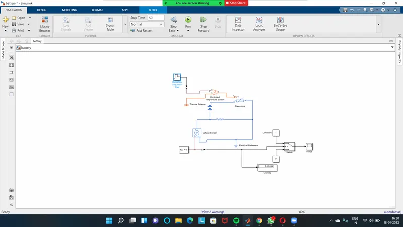
SIMULINK MODEL :-
OUTPUT
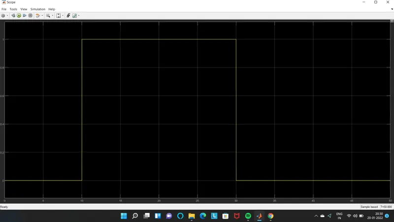
CONCLUSION:
For Thermistor challenge, we observed that as soon as temperature increases in the circuit, voltage value got decreased. Hence, we have used this logic to operate fan condition as when temperature is above 25 deg. celcius, voltage value is less than threhold voltage, then it triggered the switch to operate true condition as '1' and fan gets on otherwise it is off.