Week - 4
1. Implement control logic of a “washing machine” using Stateflow.
Objective:
To create a control logic for washing machine using stateflow with following conditions.
Blocks used:
i) Constant block
ii) Stateflowchart block
iii) Display block
iv) Lamp
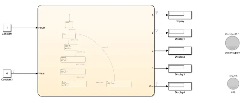
Inside the chart block control logic for the washing machine are written.
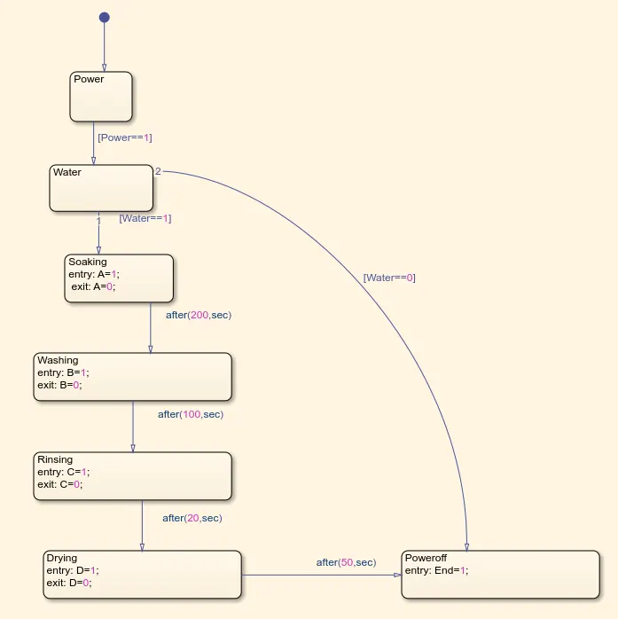
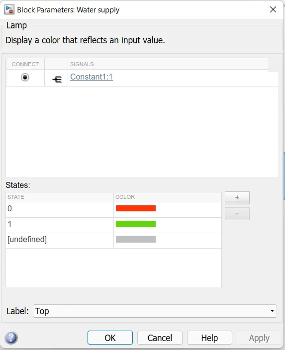
Power, Water state are created. A, B, C, D, E, End variables are created to denote the state for Soaking, Washing, Rinsing, Drying,& Poweroff. For soaking time period is 200seconds which is defined in condition, washing time period is 100seconds is defined in condition, rinsing time period is 20 seconds is defined in condition and for drying periodis 50 seconds. Totally 2 input states are there, Power & Water. 5 output states are there which shows working state of Soaking, Washing, Rinsing, Drying& Poweroff. Two lamps were used, one connected with output of poweroff and one with input of water.
Working:
when Power==1, Water==1 as input to control logic chart, state checks the condition and proceeds for soaking, washing, rinsing, drying sate. After that power should turn off. To indiacte the power off with LED, a lamp is connected with output of End state. If the Power==1, and the water supply is not available (i.e Water==0) the machine should turn off and indicate water supply is not available through LED. For that one lamp is connected with input of Water. If water==1 Green light will indicate, Water==0 Red light will indicate.
2. Make a Simulink chart for the “Gear shift” logic
Objective:
To make a Gearshift logic using simulink chart
0-15kmph 1st gear, 16-25kmph 2nd gear, 26-40kmph 3rd gear, 41-60kmph 4th gear, above 61kmph 5th gear, the speed varied while simulation is running and the gear status is displayed.
Blocks used:
i) Constant
ii) Slidergain
iii) Stateflowchart block
iv) Display block
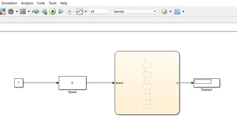
Inside chart, control logic for gear is written.
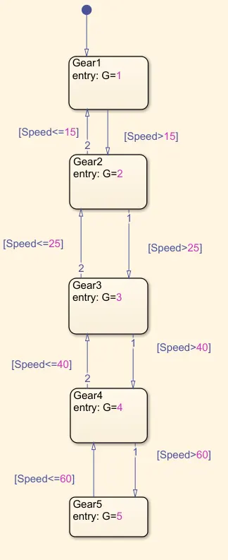
Here single input is used (i.e Speed). State blocks were created and conditions are written.
If the speed between 0-15 (1st Gear)
If the speed between 16-25 (2nd Gear)
If the speed between 26-40 (3rd Gear)
If the speed between 41-60 (4th Gear)
If the speed above 61 (5th Gear)
For Speed input, Slidergain is used. An constant block is connected as input to slidergain. Inside slidergain speed range is setted by 0 as Low and 100 as High. Inbetween the ranges we can slide using sliderbutton while the simulation is running.
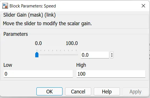
To display the Gear status, Display block is connected with output of Chart.
Working:
Before running the program Set the Run time as 'inf'. This means the program have no stop time so the program runs for more time, we can use the slider button and change the values. When the speed range is between 0-15, enters the chart and check the condition shows 1 in display block. open the slider block and drag the slider to change the value, according to the speed condition gear will be changed and notified on display block.