Week - 4
AIM:
- Implement control logic of a “washing machine” using Stateflow as per given sequence:
- If the power supply is available, the system gets activated
- If the Water supply is not available, stop the process & indicate through LED
- Soaking time should be 200s followed by Washing time of 100s.
- Then rinsing happens for next 20s & dryer runs for 50s
After all the processes have completed turn on the finished LED
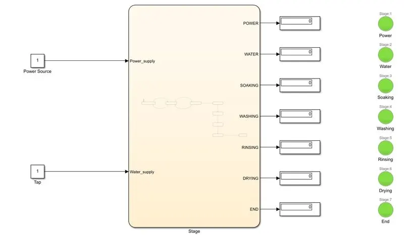
SIMULINK MODEL:
STATE FLOW CHART:
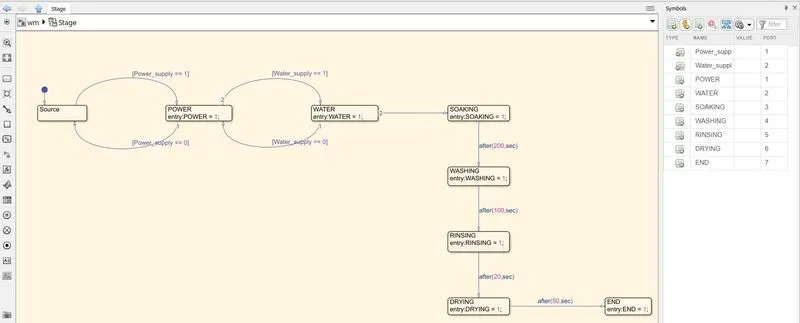
EXPLANATION: Inititially we create two constant blocks - power & water supply blocks. If 0 then, the supply is cutoff and when the value of these blocks are 1 then there are in ON condition.
We, now create a chart, inside of which we create the state flow involved in a washing machine. Having met the conditions that both power supply and water supply are present (value = 1), the control begins. Soaking, washing, rinsing and drying are conducted for the requisite times as mentioned in the problem statement. We then create the end state.
We now go to the symbols pane inorder to define the various variables. The variables power_supply & Water_supply are considered as inputs and the rest are assigned as outputs.
The outputs of the chart are connected to display blocks and further each display block is associated with a seperate lamp block, denoting green - when the process is not complete ; red - if the process has been completed.
A stop time of 400 sec is fixed and the simulation is performed and results are captured at each stage.
RESULTS: The washing machine functions according to the various time intervals as specified in the stateflow.
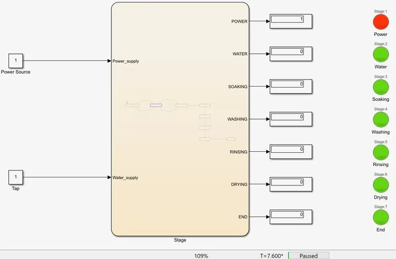
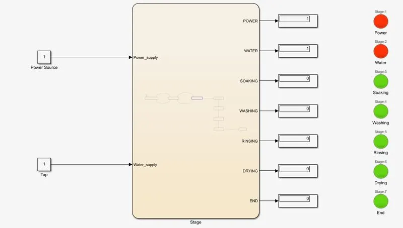
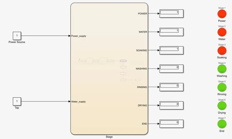
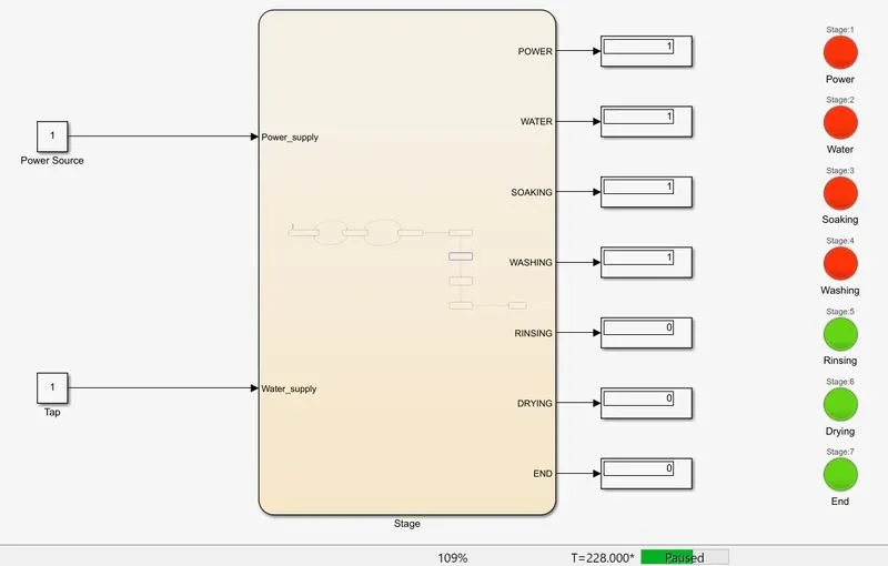
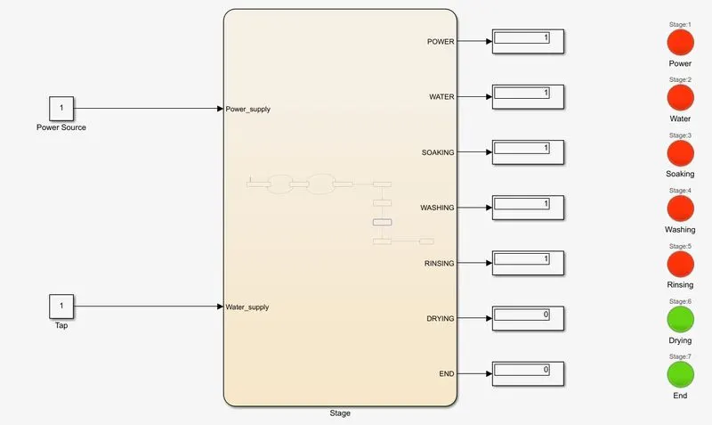
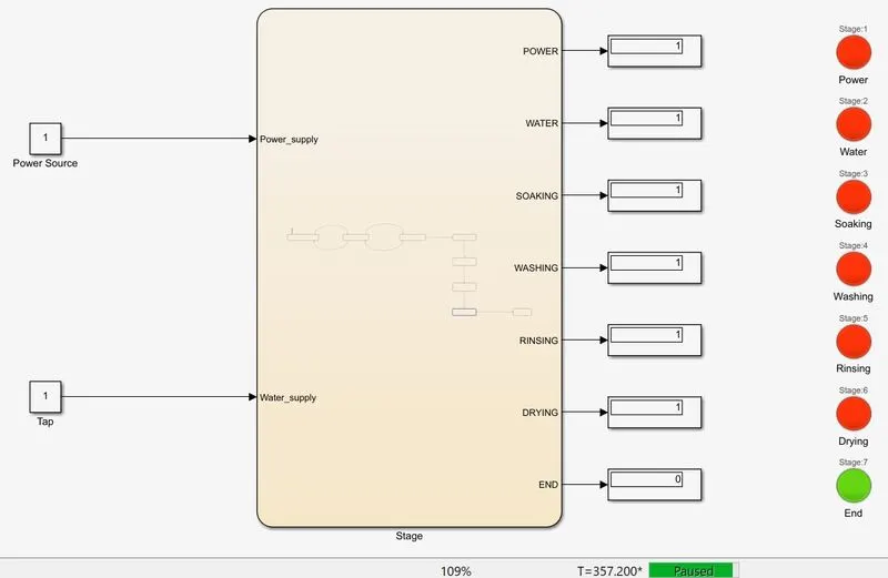
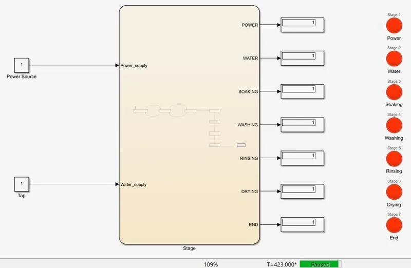
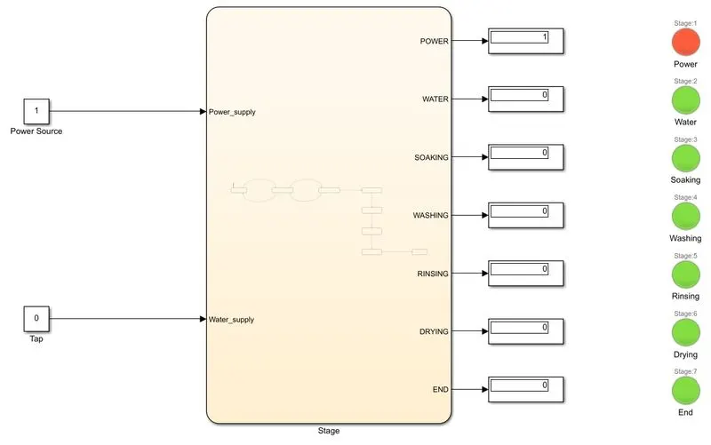
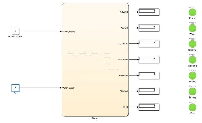
Note: The figures shown below depict the situations when either the power or water supply is cutoff.
AIM:
2. Make a Simulink chart for the “Gear shift” logic as per below conditions:
Speed Range(kmph) Gear
0 to 15 1
16 to 25 2
26 to 40 3
41 to 60 4
Above 61 5
Give speed input while the simulation is running & display the gear number.
SIMULINK MODEL:
STATE FLOW CHART:
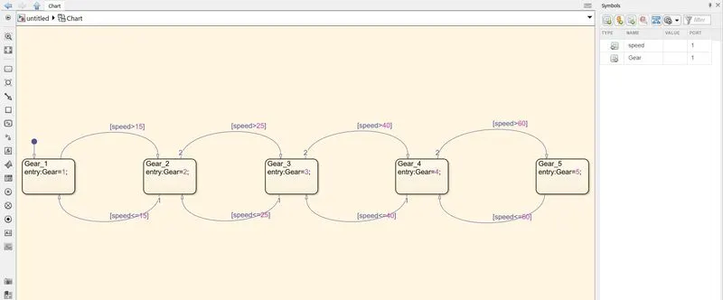
EXPLANATION:
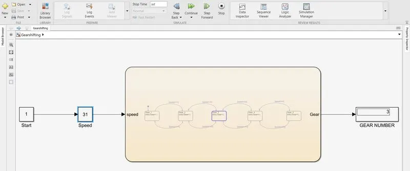
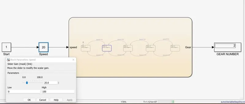
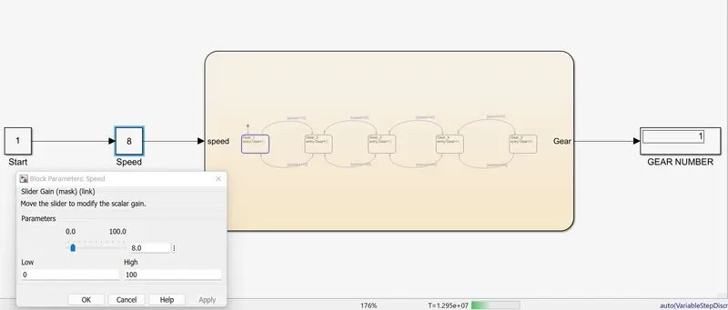
The above simulink model is made using constant blocks depicting start(key - value =1), slider gain block - to assign various speeds while running the simulation,chart and display block to depict the gear number used.
Inside the chart, the state flow is made using state blocks each corresponding to a different gear number form 1 to 5.
The variable 'gear' is assigned to be the output and 'speed' is considered as the input.
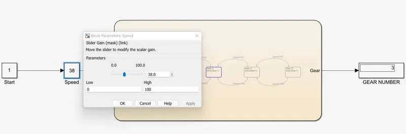
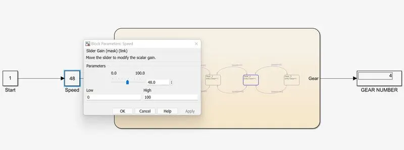
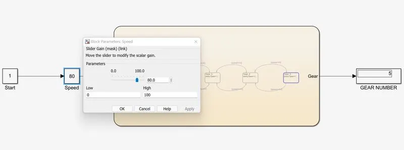
The simulation stop time is set to infinite and the speed is varied inside the slider block at various intervals and the gear number is verified.
RESULTS:
LINKS:
1. WASHING MACHINE
https://drive.google.com/file/d/1jC9DPVgtmNrfVetrReP1-oD5hLlSY3eS/view?usp=sharing
2. GEAR SHIFTING
https://drive.google.com/file/d/1smbCGMGGOYUroBIGwZqUzCnUZWQgK4Un/view?usp=sharing