Week - 4
Part1:
Aim: To implement control logic chart for Automatic Washing machine using stateflow in simulink.
Method/Process:
- Create a blank model in simulink
- open chart block from stateflow in library browser
- Select junction feature in stateflow window
- Enter the control logic as follows:
1. Soaking = first 200secs
2. Washing = 100 secs
3. Rinsing = 20 secs
4. Drying = 50 secs
- Once the control logic is entered run the operation for 370 secs
Blocks used:
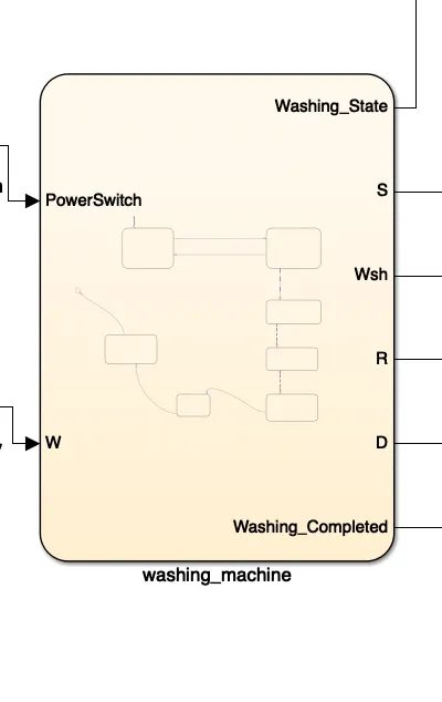
Chart:
- Chart block is used to represent an event driven system.
- In event driven system th system responds to an event by transition from one state to another
- The transition occurs if the governing condition defining the change or transition is true
Display:
- Display is used to show the result of the input data
- For numeric data we can select the output format of display
Constant:
- Constant block is used to provide real constant values
- This block is used to provide Constant Signal output
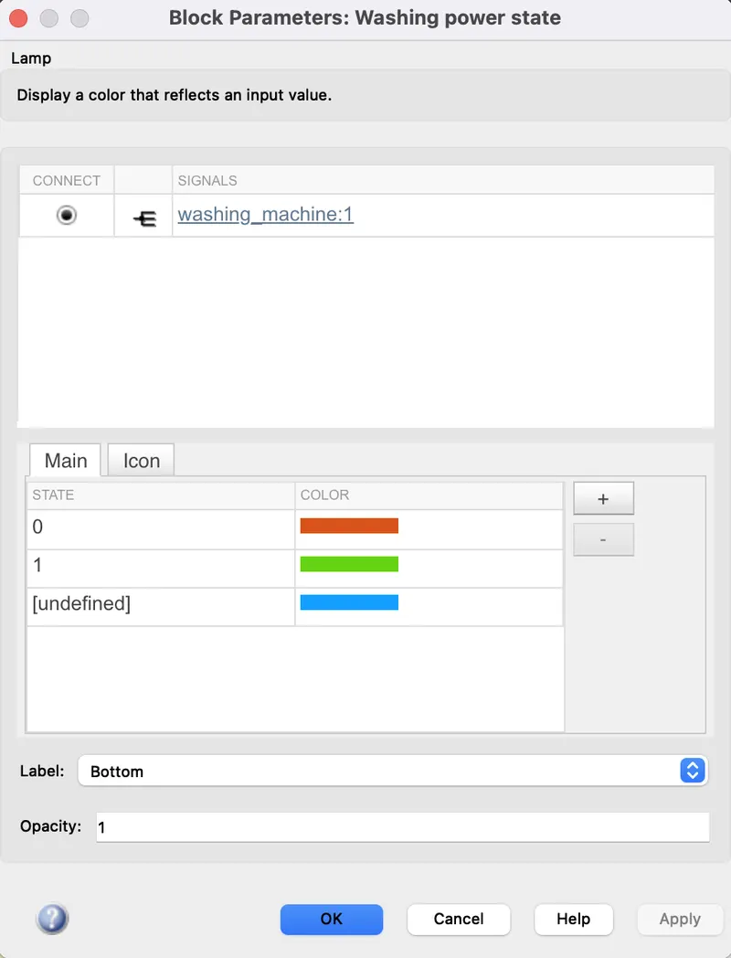
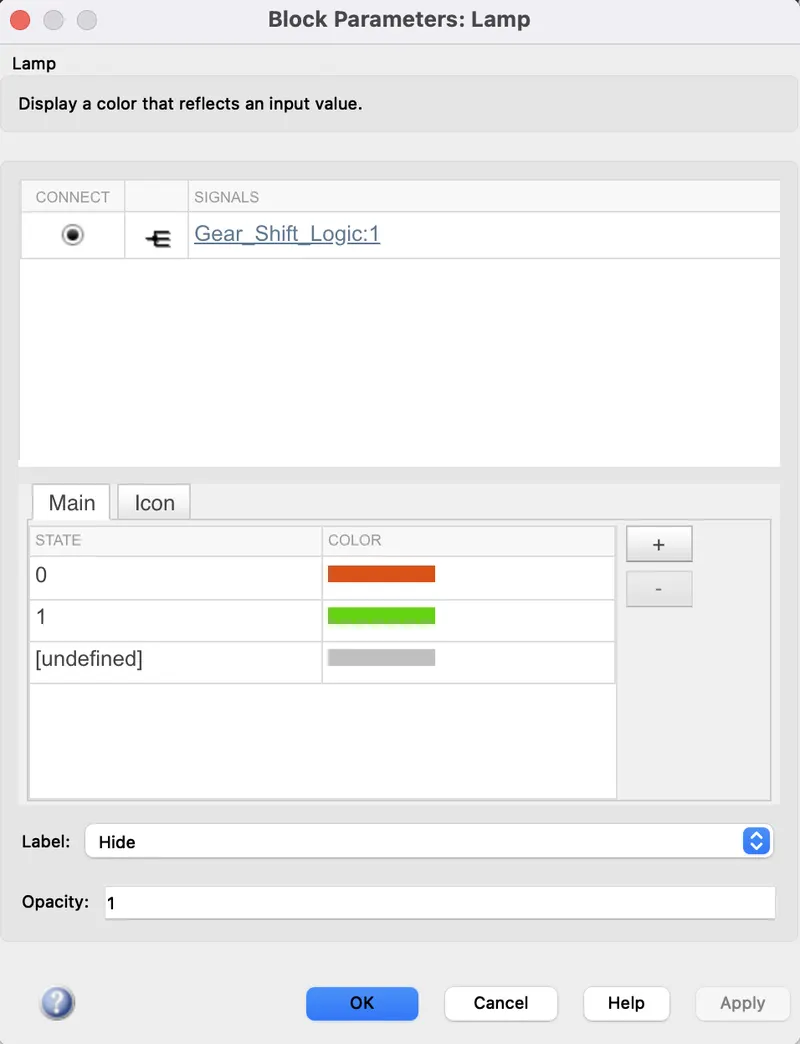
Lamp:
- It is used to display color indicating the Value
- Lamp can Display the change in state
- We can specify the values for input and colors to provide the informstion during simulation
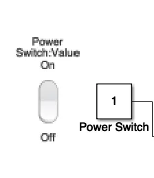
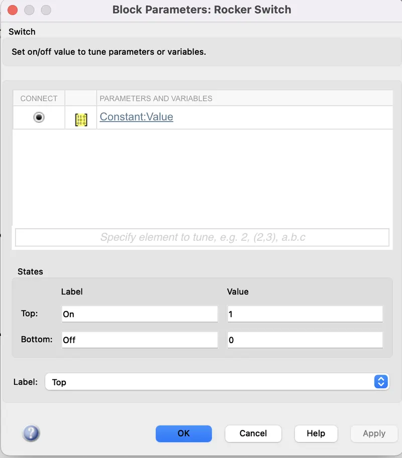
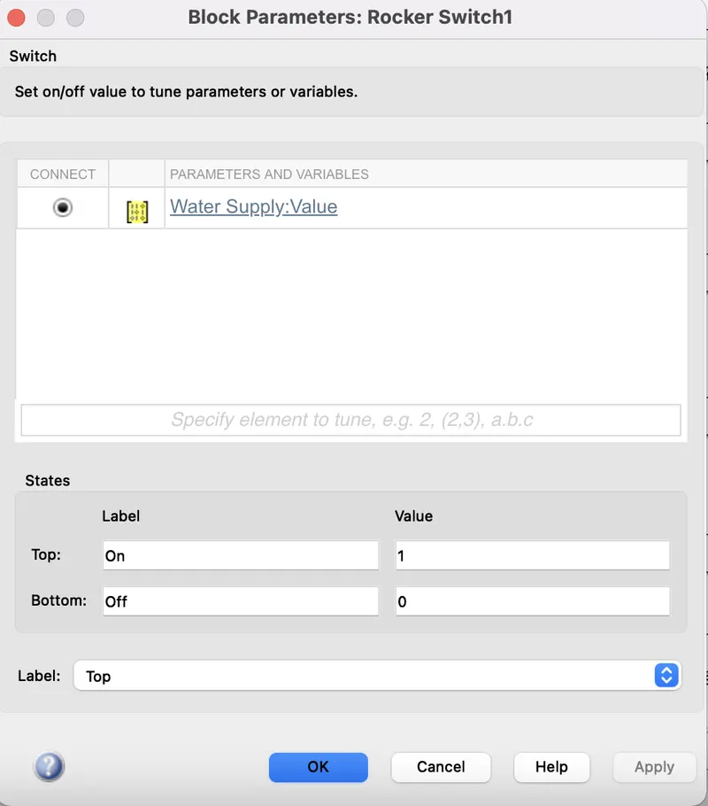
Rocker Switch:
- The switch toggles the value of the connected block between two values during simulation.
- we can connect Rocker switch to a switch block in model to change model state during simulation
Logic:
Rocker switch is used with a constant to supply power and water. A lamp is used to indicate the status of completion of a state in the system. Eg:Power supply is checked for every state and water supply is also checked for soaking washing and rinsing
The input time for every state is given and the status of running is seen by the indicator of the lamp corresponding the process
Simulink logic chart for washing machine:
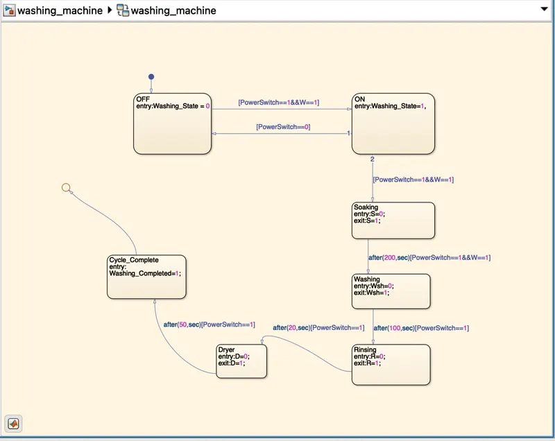
Above chart state 1 is made by 2 conditions of power which corresponds to values (PowerSwitch==1) and water supply(W==1)
If both power and water at entry is 1 then machine gets activated and next process is started
After this 4 states are created such as Soaking,Washing,Rinsing,Drying with the time as 200 sec soaking,100 sec for wash,20 sec for rinse & 50 sec for drying. Entry and exit conditions are 0 and when process completes they become 1.
After completion of processes the led glows green indicating the completion of process.
Symbols Pane:
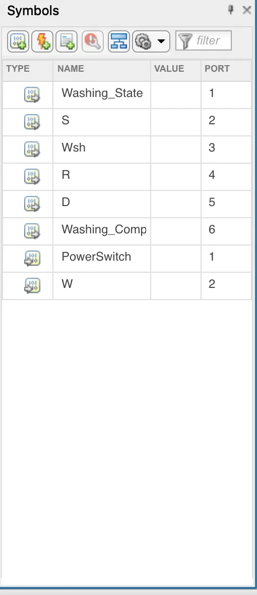
In symbols pane PowerSwitch & W are given as input and rest of the states are outputs
Simulink model for washing machine completing washing:
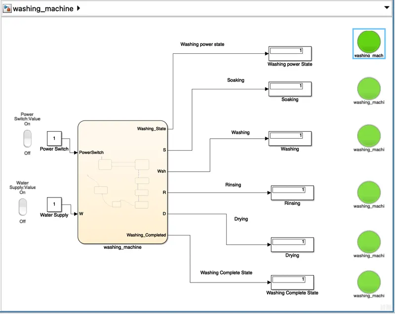
In above chart it is shown that when all LED are green then all processes are completed and output 1 from display also indicates the same.
Part-2:
Aim: To create a simulink model using stateflow for "Gear shift" with below conditions
Speed Range(kmph) Gear
0 to 15 1
16 to 25 2
26 to 40 3
41 to 60 4
Above 61 5
Process:
- Create a blank model and in chart block select the features of stateflow window
- Control logic is that the gear should be changed based on the above conditions
- That is it should increase with increase in speed and decrease with decrease in speed
- After the control logic the stateflow is run for infinite time
Blocks used:
Chart:
- Chart block is used to represent an event driven system.
- In event driven system th system responds to an event by transition from one state to another
- The transition occurs if the governing condition defining the change or transition is true
Display:
- Display is used to show the result of the input data
- For numeric data we can select the output format of display
Constant:
- Constant block is used to provide real constant values
- This block is used to provide Constant Signal output
Lamp:
- It is used to display color indicating the Value
- Lamp can Display the change in state
- We can specify the values for input and colors to provide the informstion during simulation

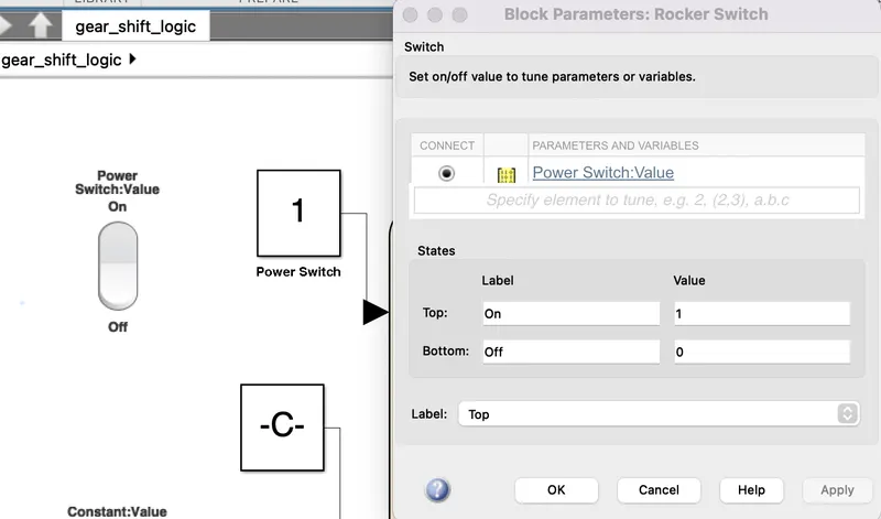
Rocker Switch:
- The switch toggles the value of the connected block between two values during simulation.
- we can connect Rocker switch to a switch block in model to change model state during simulation
Slider Switch:
- Slider block tunes the value of the block parameter to a gain block or constant block
- The range can be modified to fit the data
- It is used to control the model
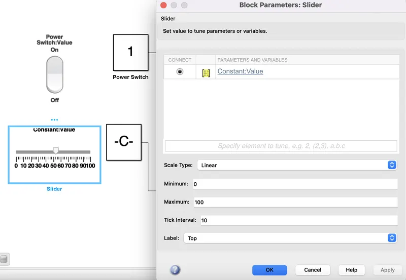
From slider block we can change input while the simulation is running.
Logic of Gear Shift:
- Speed range is from 0 to 100 and slider switch is used to vary input
- Gear first is from 0 to 15 and second is 16 to 25 and third is 26 to 40 and so on
- The entry and exit condition are specified for each gear and mapped out to lamp and dosplay block.
Logic chart:
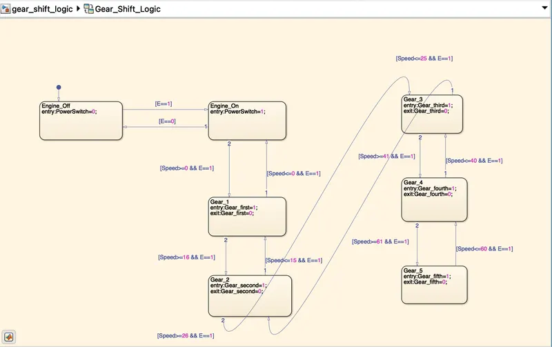
In the above chart initially Engine is started from input switch through Rocker switch an dthen Gear shift logic is implemented using the gear states
Gears 1,2,3,4,5 respectively for speed ranges are created with transition
For shift up
Speed >15 G=2
Speed >25 G=3
Speed >40 G=4
Speed>60 G= 5
For shift down
Speed<60 G=4
Speed <40 G=3
Speed <25 G=2
Speed <15 G=1
Condition E==1 is given with various input values of speed
Symbols Pane:
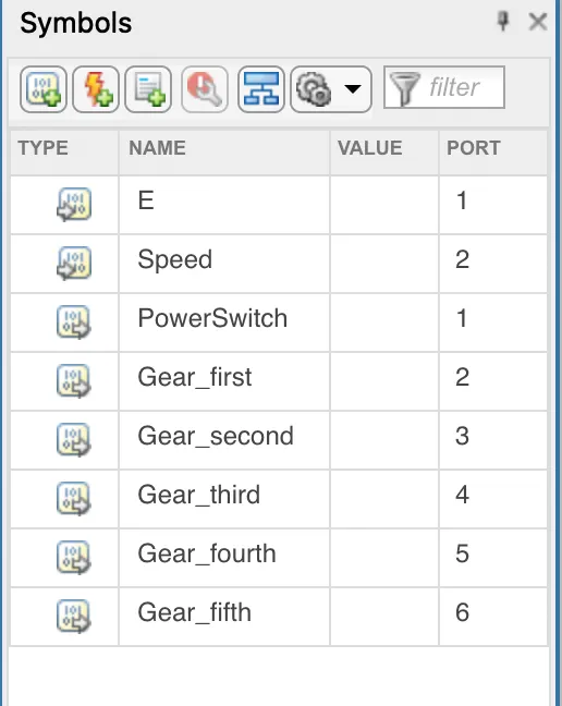
Engine and speed is given as input and Power switch and gear shifts are outputs
Simulink model at different speeds:
At Speed = 52kmph
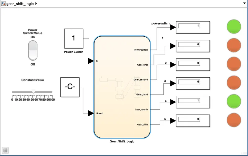
At 52kmph gear 4 lamp is glown
At Speed = 70kmph
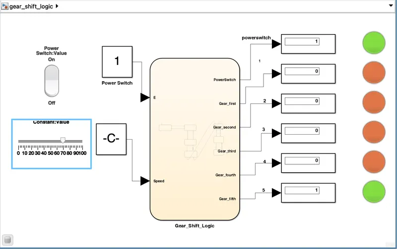
At 70kmph gear 5 lamp is glown
At Speed = 28kmph
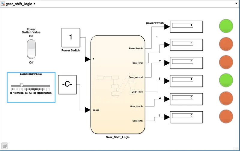
At 28kmph gear 3 lamp is glown
Thus the conditions are Simulated successfully