Week - 4
AIM:
1) To Implement control logic of a 'Washing machine" using Stateflow
2) Make a Simulink chart for the “Gear shift” logic as per below conditions
OBJECTIVE :
'Washing machine" using Stateflow :
- If the power supply is available, the system gets activated
- If the Water supply is not available, stop the process & indicate through LED
- Soaking time should be 200s followed by Washing time of 100s.
- Then rinsing happens for next 20s & dryer runs for 50s
“Gear shift” logic as per below conditions:
Speed Range(kmph) Gear
0 to 15 1
16 to 25 2
26 to 40 3
41 to 60 4
Above 61 5
Give speed input while the simulation is running & display the gear number.
THEORY
Washing machine :
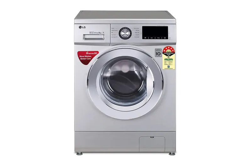
A washing machine (laundry machine, clothes washer, or washer) is a home appliance used to wash laundry. The term is mostly applied to machines that use water as opposed to dry cleaning or ultrasonic cleaners. The user adds laundry detergent, which is sold in liquid or powder form, to the wash water.
Gearbox:
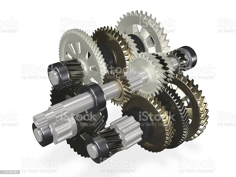
A manual transmission (also known as a manual gearbox; abbreviated as MT) is a multi-speed transmission where gear changes require the driver to select the gears by manually operating a gear stick and clutch (which is usually a foot pedal for cars, or a hand lever for motorcycles). Early automobiles used sliding mesh manual transmissions with up to three forward gear ratios. Since the 1950s, constant mesh manual transmissions have become increasingly commonplace and the number of forward ratios has increased to 5-speed and 6-speed manual transmissions for current vehicles.
The alternative to a manual transmission is the automatic transmissions; common types of automatic transmissions are the hydraulic automatic transmission (AT), automated manual transmission (AMT), dual-clutch transmission (DCT), and the continuously variable transmission (CVT).
WASHING MACHINE MODEL :
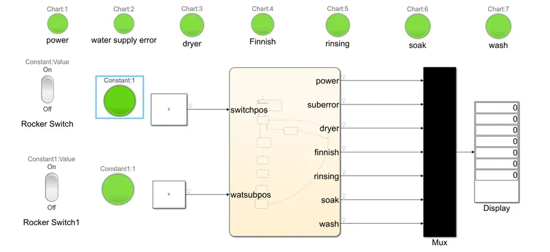
The washing machine model is compromised of several LEDS,and two rocker switches and the state flow chart ,and a display and a mux block.
Steps:
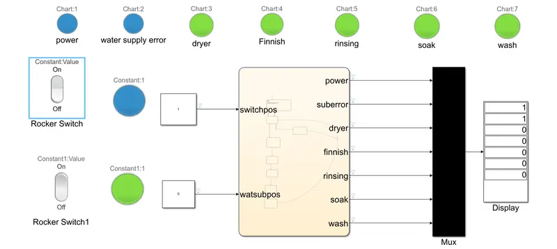
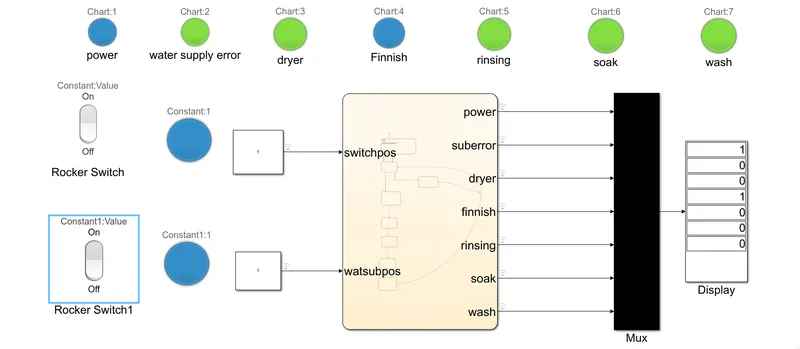
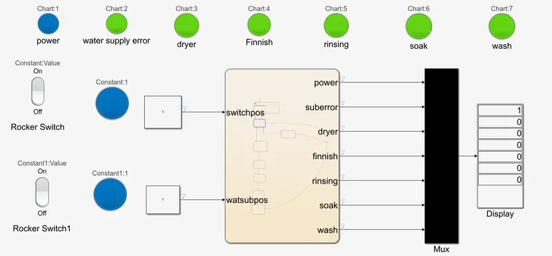
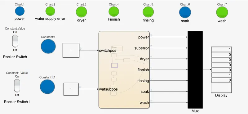
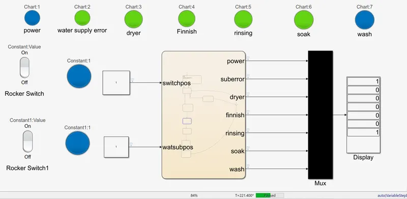
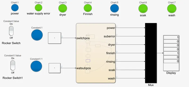
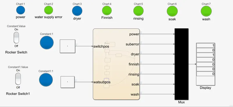
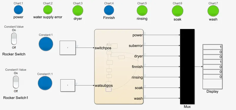
The input signals are inputted through the swiches,then it is picked up by the connected leds.The Leds are green when there is no signal and blue when a signal passes through them Then it goes into the state flow chart,then all the outputs go through the other end and they trigger the Led's connected with them and then go through the mux which combines all the output signals into a single signal which can be easily connected to the display which displays an array of output data. The display shows 0 when when there is no signal in the respective output port and 1 when there is a signal in the respective output port.
Sate flow model diagram:
Steps
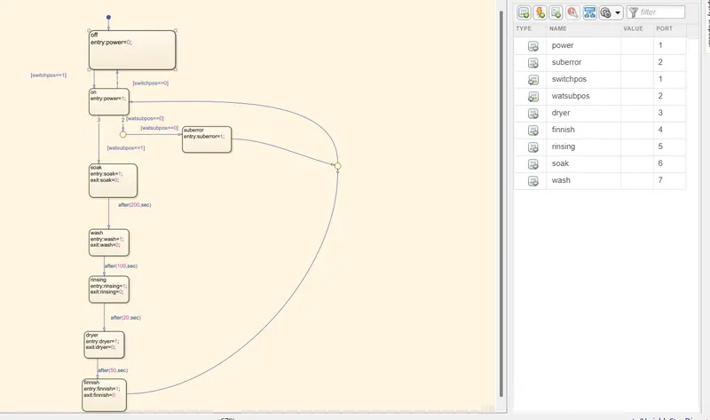
-initially the system is off
-Then when power is on ,it activates the corresponding led and it is transferred from the off state to the on state
-Then it checks if water supply is available, if it is available, it starts the soaking process, if not it will output "suberre and trigger the water supply led and then it is returned to the on state through the junction.
-up to this moment the system is event triggered from now on it is time triggered
-then it will start the soaking process and trigger the corresponding Led, then after 200 second it ends the state and as it exits it will stop this process which will deactivate the corresponding Led
-Then it will start washing for 100 seconds, and as it exits it will stop the process
- Then it will start rinsing for 20 seconds, and as it exits it will stop the process
- Then it will start during for 50 seconds, and as it exits it will stop the process
-Then it will turn the finish Led
-Then it is returned to the on state through the junction.
Model verification user control cases: All system is off:
System is on and water supply is off:
The system gives water supply Problem error
System is on and water supply is on:
The system works normally and finishes the program
Step by step detailed system verification:
In order to verify that the system is working fine and performing all the functions we make it run in steps:
Step1:
The system is ON
Step2:
It will start the soaking process after verification there is a water supply, this step will take 200 seconds
Step3:
Then it will start the washing process this step will take 100 seconds
Step4:
Then it will start the rinsing process this step should take 20 seconds
Step5:
Then it will start the ddrying process, this step takes 50 seconds
Step6:
Then it activates the finish lamp
GEARBOX MODEL :
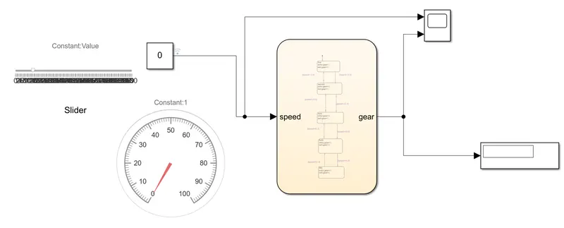
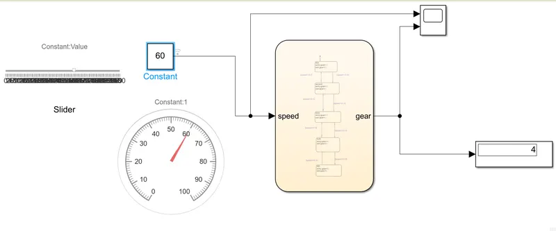
The gear box model uses slider as a speed input in order to simulate the throttle ,and gauge connected to the same signal in order to display the inputted speed value, the output is then displayed on an a display and a scope is connected to see the speed and gearshift outputs.
GEAR box Sate flow model diagram:
Steps:
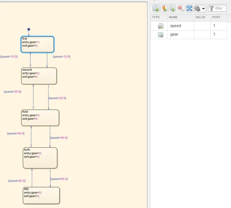
-At first gear is selected and the car will remain in this gear until the speed exceeds 15.9kmphthen it will shift to the second gear,and as the system is exiting this state it will disengage the first gear.
-On the other hand if the vehicle was in second gear and decelerated to less than 15.9 kmph, the system will make shift to the first gear and as it is exiting from the second state it will disengage the second gear.
-Then it will shift to third when the speed is higher than 25.9 kmph gear, and as the system is exiting this state it will disengage the second gear.
-On the other hand, if the vehicle was in third gear and decelerated to less than 25.9 kmph ,the system will make shift to the second gear and as it is exiting from the third state it will disengage the third gear.
-Then the speed exceeds 40.9 kmph then it will shift to the fourth gear, and as the system is exiting this state it will disengage the third gear.
-On the other hand, if the vehicle was in fourth gear and decelerated to less than 40.9 kmph kmph ,the system will make shift to the third gear and as it is exiting from the fourth state it will disengage the fourth gear.
-Then when the speed exceeds 60.9kmph then it will shift to the fifth and final gear, and as the system is exiting this state it will disengage the fourth gear.
-On the other hand, if the vehicle was in fifth gear and decelerated to less than 60.9 kmph ,the system will make shift to the fourth gear and as it is exiting from the fifth state it will disengage the fifth gear.
-All the output is stored in the same variable to be able to display all the gear shifts on a single display
-The stop time is made to inf inorder to enable user control of speed while simulation is running
USER CASE 1 -

USER CASE 2 -
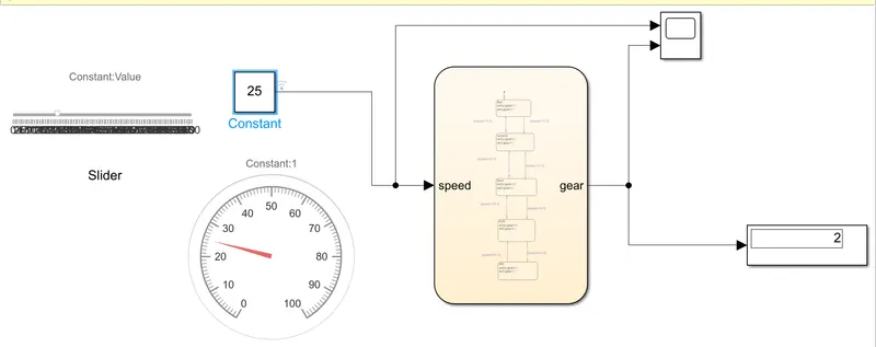
USER CASE 3 -
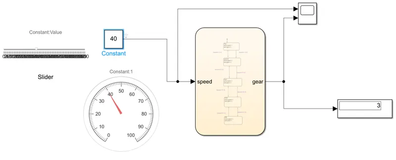
USER CASE 4 -
USER CASE 5 -
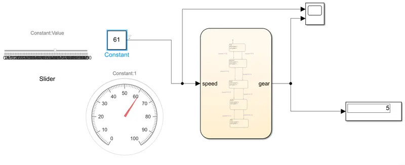
Gear shift Visualization : Initially first gear is selected, then at speed of 16 kmph it shifted to second gear, then at speed of 26 kmph it shifted to third gear then at speed of 41 kmph it shifter to fourth gear then at speed of 61 kmph it shifter to fifth gear, and it remained at this gear even with the speed increasing and reaching 100kmph.
REFERENCE:
Matlab help
Model links-
https://drive.google.com/drive/folders/1lU9GKtG87ajvgb4qOHCBD-e-rItFHp40?usp=sharing