Week -2
Aim:
- To simulate a Simulink model of a Doorbell using Solenoid block and observe the output
Objective:
- To create a situation where the switch is closed for 2 seconds and then released. To observe the physical movement of the plunger.
Introduction:
Part 1: Doorbell
A simple construction of a doorbell is as shown in the figure [1] below.
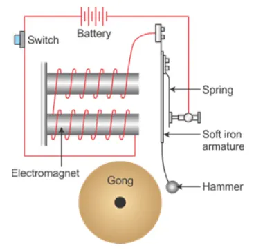
When the switch is pressed the circuit is completed and the electromagnet is activated which makes the hammer strike the bell. The armature is made of iron which attracts the magnet when the circuit is completed. This hammer is an iron ball that strikes on the bell. The iron armature is connected to the spring which maintains its position and not always in contact with the bell.
Solenoid:
A solenoid is nothing, but a copper wire wounded around the solenoid iron core which turns into a magnet when electricity is passed through it. The iron core demagnetises once the electricity is cut off [2]. A simple solenoid construction is shown in the figure below.
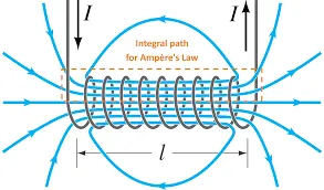
A solenoid is used in various fields such as in electrical appliances, automotive and aerospace applications, heavy machinery applications and much more. Solenoids are very beneficial as it has a very compact design plus having a controlled magnetic field which is only activated once the electricity is passed through it. The wire wrapped around the cylinder, the magnetic field because of the wires can become quite strong. More number of loops of wire stronger the magnetic field created. The formulae [3] for the magnetic field created inside the solenoid is as below:
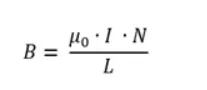
Where,
- B = magnetic field (N/Amp m)
- μo = permeability of free space
- I= current (Amp)
- N = number of loops
- L = length of the solenoid
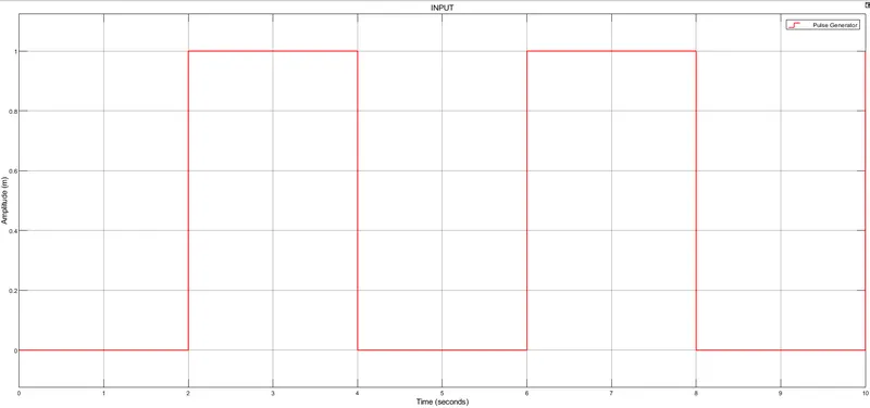
MODEL INPUT
STEPS :
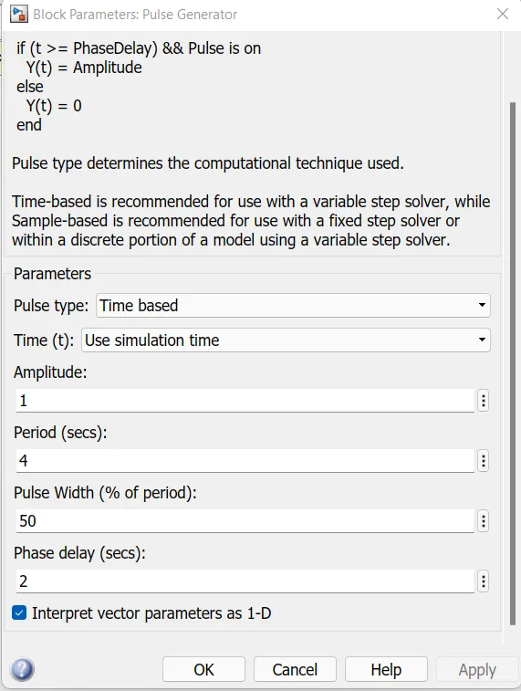
Input parameters pluse
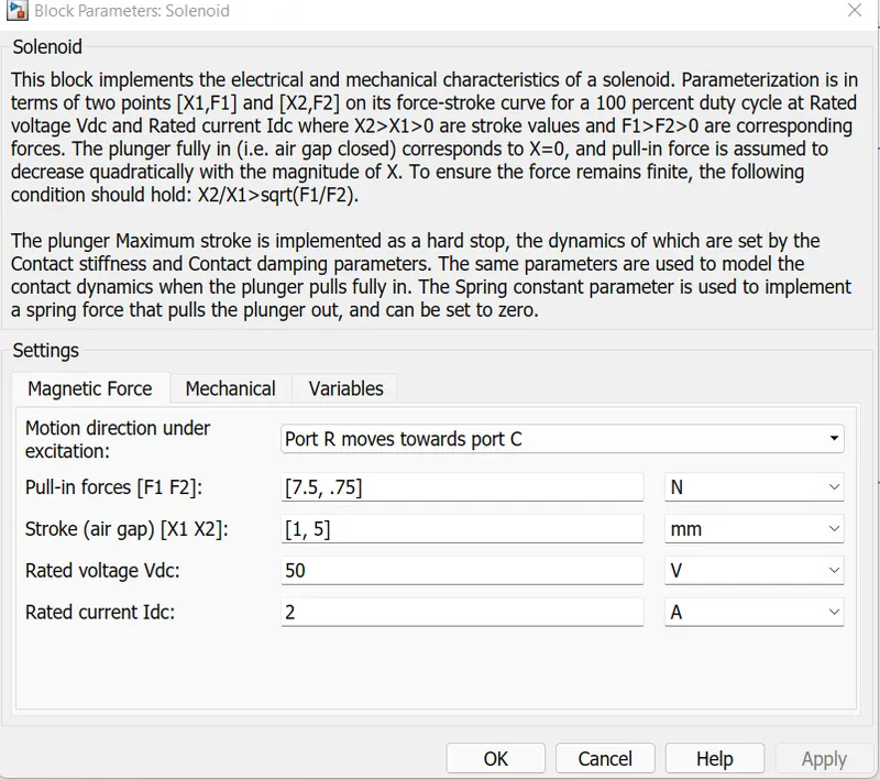
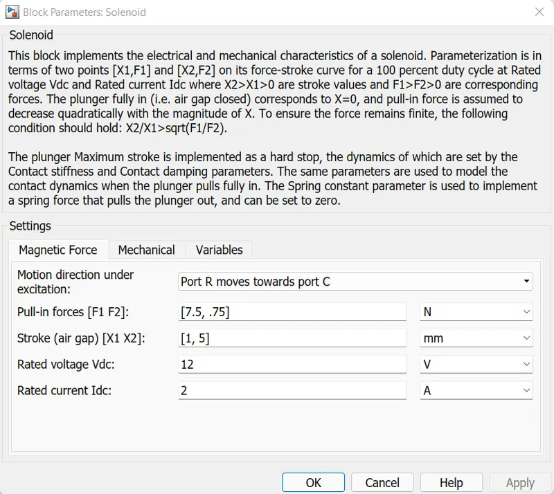
Input Values of solenoid
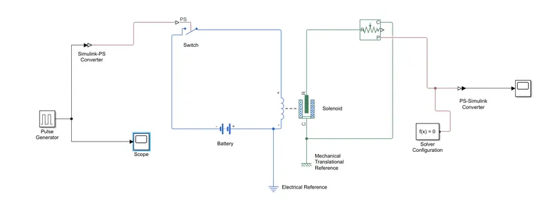
- A pulse generator is used to simulate the pressing of the bell switch it has a period of 4 seconds and a duty cycle of 50%,so it will remain open half of the wavelength and a delay of 2 seconds(not required)
- Then Simulink-ps converter is used to convert the Simulink signal to physical signal
- This is then connected to a switch controlled by external physical signal with all of its settings left in default, the switch is closed when it receives the signal, otherwise it is open
- This is connected to a battery and then the whole circuit is grounded by an electrical reference
- Then the battery and the switch were connected to the positive and negative terminals of the left side of the solenoid block, then the case terminal was connected to a mechanical translational reference, all the settings of the solenoid were left in default
- Then in order to detect the movement of the solenoid, an ideal motion translational sensor was used, its reference is connected to the reference of the solenoid and its case was connected to the mechanical translational reference, all of its settings were left in default
- Then a signal is taken from the p port which measure the displacement and connected to the solver configuration block which is required as each and every Simscape circuit needs to be attached with the solver configuration block as it specifies the solver parameters that the model needs before beginning the simulation
- Then the signal is Converted to Simulink signal via ps Simulink converter ,and then it is connected to a scope to display it.
OUTPUT :
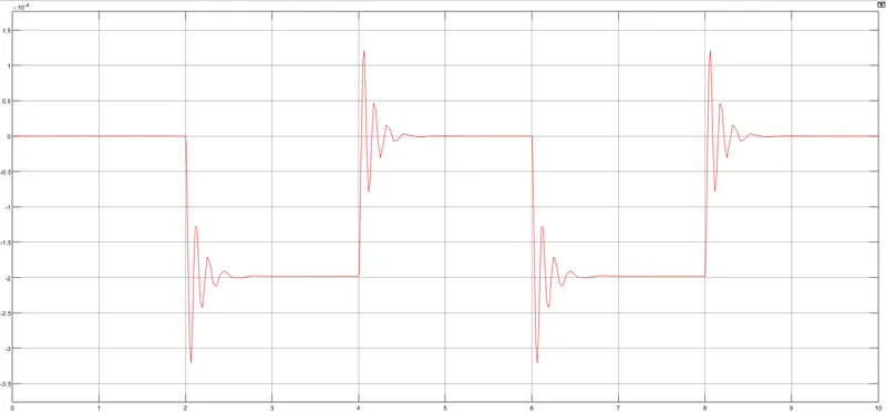
Fig- 50v solenoid output (Displacement vs Time )
The output follows the input signal except for the fluctuations related to the mass of plunger and spring stiffness and damping, the open fluctuations can be damped it the solenoid rating voltage is the same as the battery 12v output
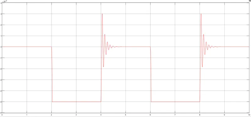
Fig- 12v solenoid output (Displacement vs Time )
CONCLUSION:
Giving input as time period for 2 seconds in the pulse generator to open & close the switch. When the switch is closed the solenoid block receives electrical power from the battery and plunger moves from port R to port C to hit the bell & produce sound. Physical movement of the plunger is observed by using translational motion sensor & physical output is converted into Simulink output model is displayed in the scope. By reducing the spring constant value and increasing the damping value vibrations will be reduced.
PART 2 :
AIM:
To simulate working of a fan under different conditions using a Thermistor in Simulink.
Objective:
To turn on the fan if the temperature is above 25 °C else off. To use the temperature source to simulate temperatures, from 0 to 10 seconds at 20 °C, from 10 to 30 seconds at 27 °C and from 30 to 50 seconds at 23 °C.
Introduction:
Thermistor is a thermally sensitive resistor which exhibits a precise and predictable change in resistance proportional to small changes in the surrounding temperature. The word "Thermistor" is derived from "thermally sensitive resistor", whose resistance change with the change in temperature. Thermistors are very sensitive to the change in temperature therefore they are perfect to detect the changes in the temperature while recording the temperature or to operate electrical appliances such as AC, fan, oven, automotive and aerospace applications. There are a vast range of applications where thermistors can be used, and different sizes and shapes of thermistors are available in the market depending upon the applications.
There are mainly two types of thermistors, NTC and PTC.
NTC: Negative Temperature Coefficient Thermistor
PTC: Positive Temperature Coefficient Thermistor.
In this study NTC type thermistor is used. This thermistor uses the B-parameter equation, where the resistance at temperature T is given by:
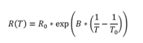
Where,
Ro = nominal resistance at the reference temperature
To = reference temperature
B = characteristic temperature constant
T = sensed temperature The default values of Ro, To, and
B in the thermistor block of Simulink are 1000 0, 298.15 K, and 3500 K, respectively.
FULL FAN MODEL :
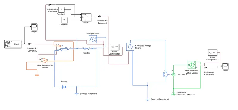
Explanation and the blocks used in this model:
1. Signal builder
2. Controlled Temperature source
3. Thermistor
4. Resistor
5. Voltage sensor
6. Dc motor
7. Switch,constant,display and scope
• First we used the signal builder to feed the given conditions of the heater at which the thermistor has to sense the temperature(i.e from 0 to 10 sec the temperature is 293 k ,from 10 to 30 sec the temperature is 300k and from 30 to 50 sec temperature is 298k)
• Then we used controlled temperature source which take the input values and translate it and feed to the the thermistor.
• Thermistor sense the temperature which has been input in the system and gives output as per that.
• Resistor and voltage sensor is used to pass the temperature output values to the switch and voltage sensor around resistor sense the voltage across it .
• Dc voltage source supplies 12 v supply to the circuit.
• As switch gets the threshold value greater than equal to constant then it on the fan at 298k.The 2 constant used in system is that if threshold value is greater than so it will give 1 value or it will give 0 value if it does not satisfies the given condition.
• Scope is used to get desired output graph so we can determine the inputs and output are satisfied or not.
INPUT :
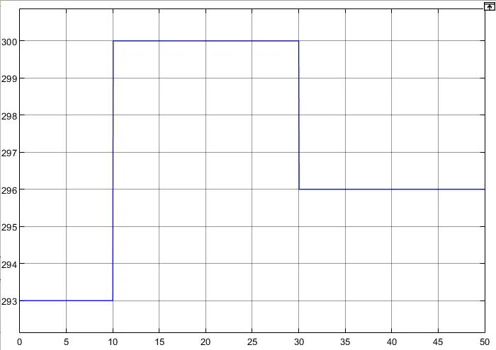
GRAPH - Temperature (k) VS Time (s)
STEPS: -
- Signal builder is connected instead of the constant where a signal of time value [0 10 10 30 30 50] and a temperature values of [293,293,300,300,296,296] were used to generate a signal
- The simulink ps converter was configured differently to take the first derivatives in order to provide enough inputs and to provide the derivatives required -Also the voltage sensor output was connected to a switch that only opens at the threshould voltage which is configured at 0.01189 voltage,so it will change the ouput from zero to one which are represented by the constants when it receives a signal with a value greater than the threshould
- Then the signal is converted to a physical signal to control the voltage source
- This was then connected to control voltage source ,which is connected to a positive and negative terminal on the left side of a dc motor which represents a fan -This circuit was then grounded to electrical reference
- Then on the left part of the dc motor block its c (case) port was connected to a mechanical rotational reference. And in order to detect and measure the angular velocity of the motor, its r port was connected to the r port of ideal rotational sensor.
- then the case port was connected to the same mechanical rotational reference as the case of the motor
- Then the output was taken from the w port which measures the angular velocity, then this as connected to the solver configuration block as each circuit should be connected to one
- Then its signal was converted to Simulink signal and then it was displayed on a scope -Then simulation time was changed to 50 seconds to capture all the events
OUTPUT :
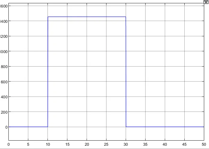
GRAPH - Angular velocity(rpm) VS time(s)
An output scope plot shown below depicts that when the temperature reached above 25'C, the DC Motor representing the fan was off for initial 10 seconds and then started working at 10th second showing around 1454.399 RPM of the motor and then, the motor turned off after 20 seconds at 30th second for the remaining 20 seconds of the time till 50th second
Conclusion:
It can be concluded that both the studies were a success where outputs observed were:
1. When a doorbell rang, a deflection was observed in the scope plot.
2. When the DC motor turned on and off when there was temperature difference was noticed by the thermistor and the switch and the RPM of the motor was observed in the scope plot in the end.
model links - https://drive.google.com/drive/folders/1SBJ4_BuJc-lMhElC5LRxR8UNU0qBSCGt?usp=sharing
Reference - Matlab help