Week - 4
Challenge 4:-
Task1:-
Implement control logic of a “washing machine” using Stateflow
* Start simulink and create a blank model.
* Search for chart block in th stateflow category of the library browser.
* Open the chart block and select the junciton feature from the state flow window.
follow the input given the task below
* If the power supply (0 and 1 switch constant ) is available, the system gets activated
* If the Water supply is not available, stop the process & indicate through LED
* Soaking time should be 200s followed by Washing time of 100s.
* Then rinsing happens for next 20s & dryer runs for 50s
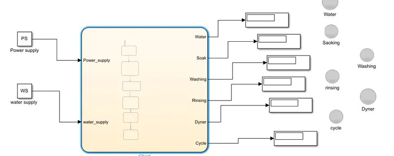
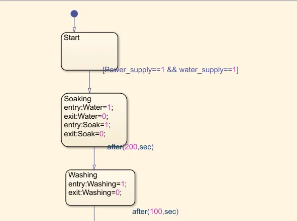
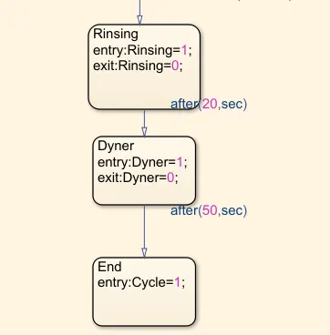
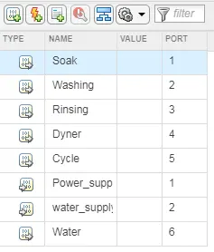
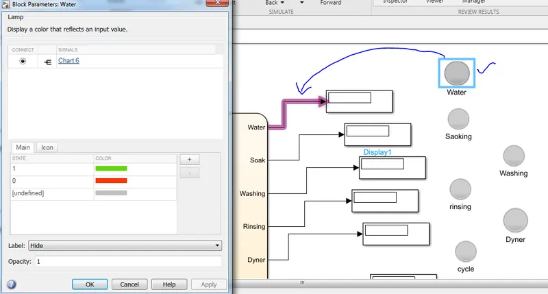
we have used the Lamps to Indicate the state or position of the washing machine
LAMP:-
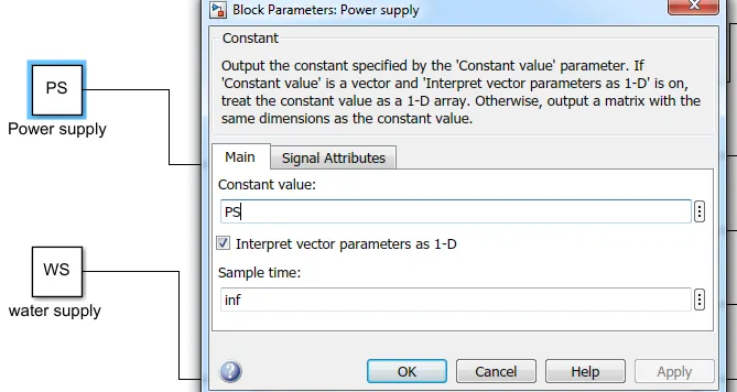
Constant to enter the on/off the washing machine
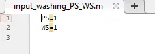
inputs for the washing machine input_washing_PS_WS.m
Results:-
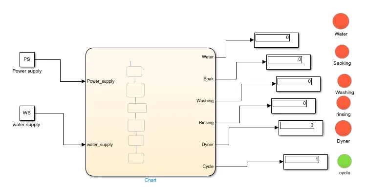
Results:-
Code,results,input .m file are attatched below
Task 2:-
Title:-
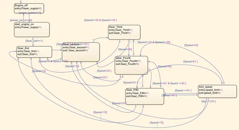
Make a Simulink chart for the “Gear shift” logic
inputs:
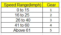
case study 1:-
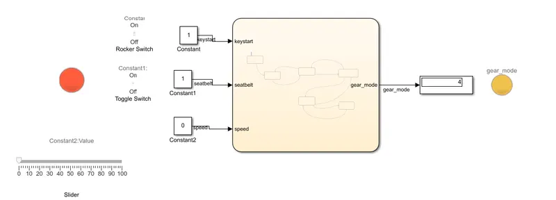
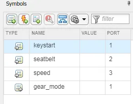
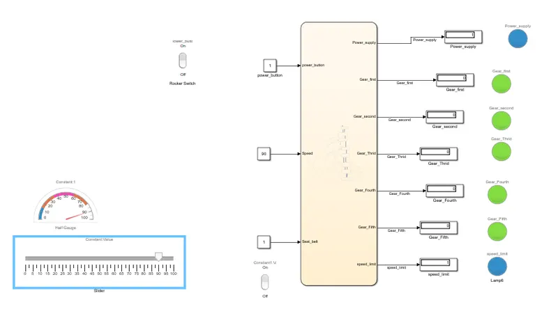
inputs:- Keystart, Seat belt , Speed
above three we have given as inputs to flow chart
keystart and seat belt is represented as constant and linked with rocker switch to ON/OFF mode
Speed is a variable constant need to give different inputs with equal interval of time
for speed input we have given the slider dashboard linked to constant
Output:- Gear mode:- To show the output as per speed the gear automatically shifts
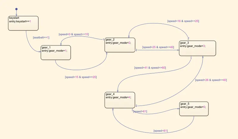
CASE study with seat belt and power button ON/OFF:-
chart:-
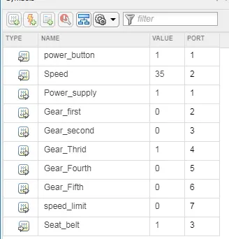
Results:-
All the results have been attached and the animation vedio also uploaded below