Week - 4
Question 1:-
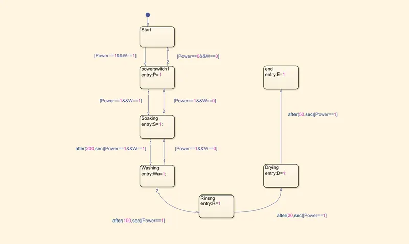
Implement control logic of a “washing machine” using Stateflow as per given sequence:
- If the power supply is available, the system gets activated
- If the Water supply is not available, stop the process & indicate through LED
- Soaking time should be 200s followed by Washing time of 100s.
- Then rinsing happens for next 20s & dryer runs for 50s
After all the process have completed turn on hte finished LED
Answer:-
State flow is a Simulink tool to implement the state machine. Here model system logic of a Washing Machine using State flow has been done.
Logic:-
When the switch is ON all system are run and its indicated through Lamp.
The water starts to enter the machine and if the water is not available, then the system will turn off automatically which will be indicated through the lamp. If the water is available then it will go on to the next step Soaking,Washing,Rinsing,Drying.
After all the process is done, then the end lamp will indicate that the process is completed.
Stateflow Chart:-
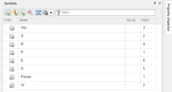
Symbols Pane:-
OUTPUT:-
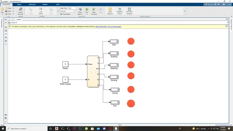
Case-1:-
If the Power Source = 0, Water Supply = 0.
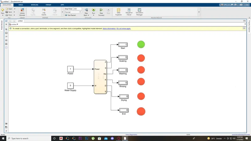
Case-2:-
If Power Source = 1 & Water Supply = 0.
Case-3:-
If Power Source = 0 & Water Supply = 1.
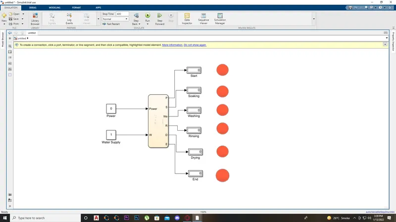
Case-4:-
If Power Source = 1 & Water Supply = 1.
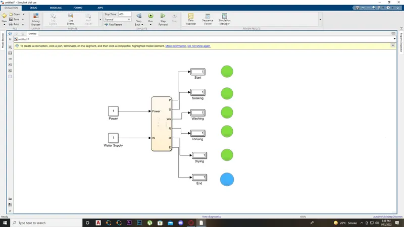
Conclusion:-
All the conditions of a Washing Machine are successfully simulated through stateflow chart.
Question 2:-
Make a Simulink chart for the “Gear shift” logic as per below conditions:
Speed Range(kmph) Gear
0 to 15 1
16 to 25 2
26 to 40 3
41 to 60 4
Above 61 5
Give speed input while the simulation is running & display the gear number.
Answer:-
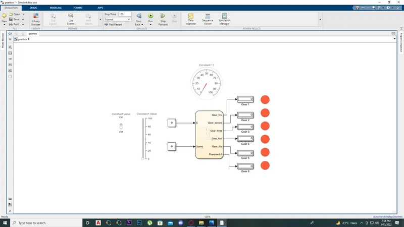
Slider block is mainly used for giving input to the speed in this system.
Logic:-
In this system speed ranges from 0-100 so we use slider block to give the input speed.
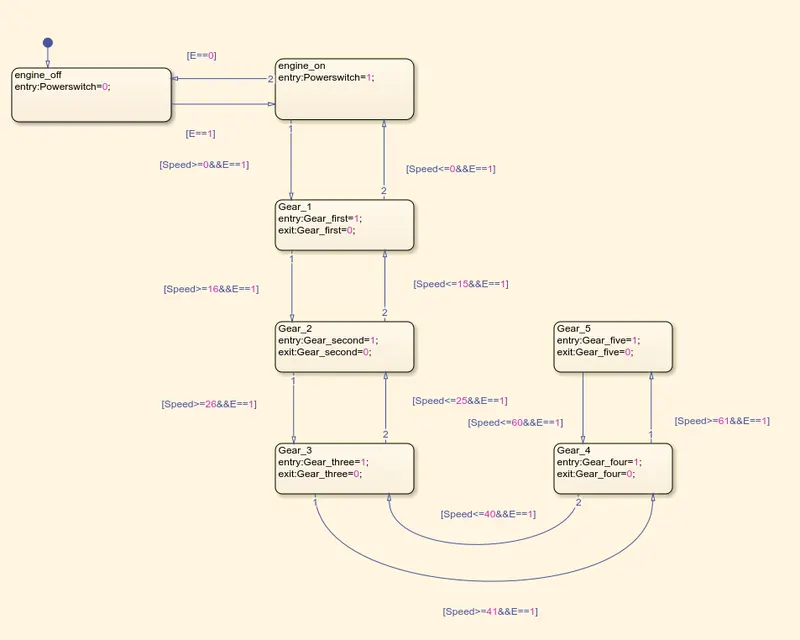
The first gear speed ranges from 0-15 so the entry of state for the 1st gear is o<=speed and 15>=speed it is the exit condition of the gear in the soeed greater than 15. Similarly all the condition for rest of the gears are configured as given in the question.The output is given to lamp and display block.
Stateflow Chart:-
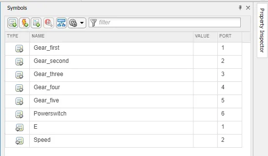
Symbol pane:-
Models:-
1. Complete Model.
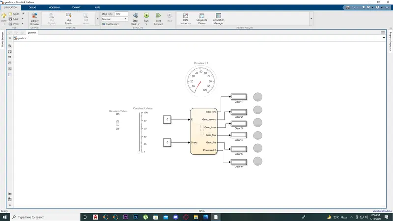
2. Gear - 1.
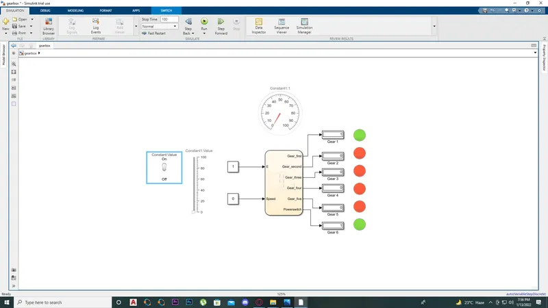
3. Gear - 2.
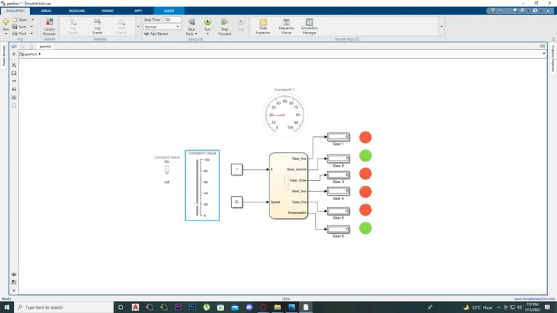
4. Gear - 3.
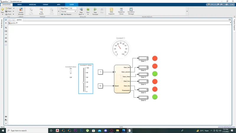
5. Gear - 4.
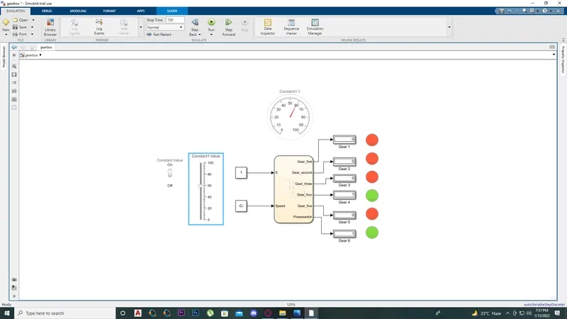
6. Gear - 5.
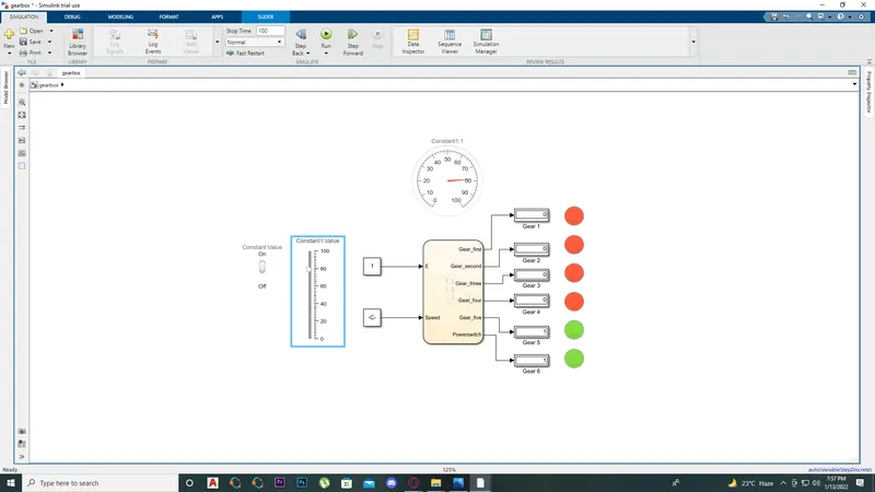
7. At maximum speed.
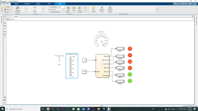
8. Ignition off - Full speed.
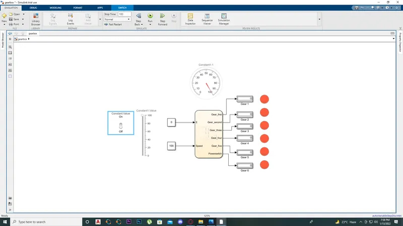
9. Ignition off - Ideal system.
Conclusion:-
Hence all the conditions are simulated successfully through state flow.