Week - 4
Ans 1)
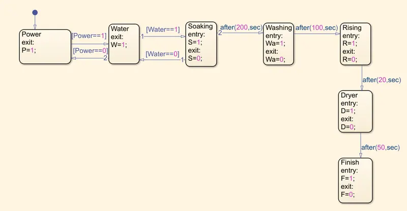
- If the power supply is available, the system get activated
- If the water supply is not available, stop the process and indicate through LED
- Soaking time should be 200s followed by washing time of 100s
- Then rising happens for the next 20s and dryer run for 50s
After all the processes have completed turn ON the finished LED
A washing machine is a machine is used to washed varies types of clothes without applying any physical efforts. With a washing machine , you don't have to rub the clothes with your hand or spin them to removed the water. The washing machine enable you to washed your clothes automatically without having to superviced its operation. All you have to do is put the clothe in the machine and select the wash mode. The washing machine automatically takes in the amount of water and detergent required and it also automatically set the timer for washing, rising, soaking and drying as per the selected mode and number of clothes.
Modelling of washing machine in simulink:
the following things we need for modelling the sub system of washing machine:-
- Toggle switch
- Constant
- State flow chart
- Lamp
- Display
State flow chart:-
-Logic of washing machine:-
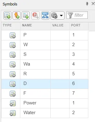
Variable chart:-
In symbol pane, We can assign what are the inputs and outputs in the logic.
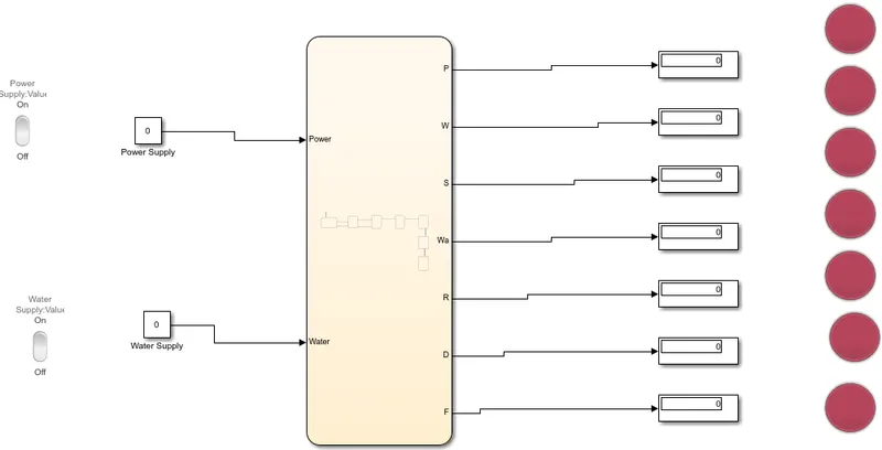
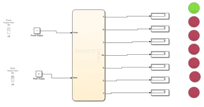
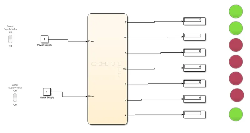
The two inputs are given for the power supply and water supply. Once the inputs are given outputs are displayed by the flow chart as per given sequence. The system are observed for some time then it is check and the process is completed by green light as lamp.
1. Condition when both the power supply and water supply are OFF:-
2. Condition when the power supply is ON and the water supply is OFF:-
3. Condition when both, the power supply and water supply are ON:-
Ans 2)
A gear shift machanism for a manual transmission include a shaft axially movable for selecting shift plane and rotatable for engaging the gears defining the ship planes.
- In this gear shifting case, We need to provide a continues variable value for the input as a speed, For that , I used a slider block as an accelerator for the speed change.
- As per our requirement , We need to display the gear number to be visible on the display block at a time of acceleration, So i used infinite times for compilation and chnage the speed manually on the slider block.
- I configure the slider block by providing a value min=0 and max=100, As the speed of the vehicle.
- I used lamp block to show if the system is ON or OFF, For economic mode, for the over speed.
Slider block configuration:-
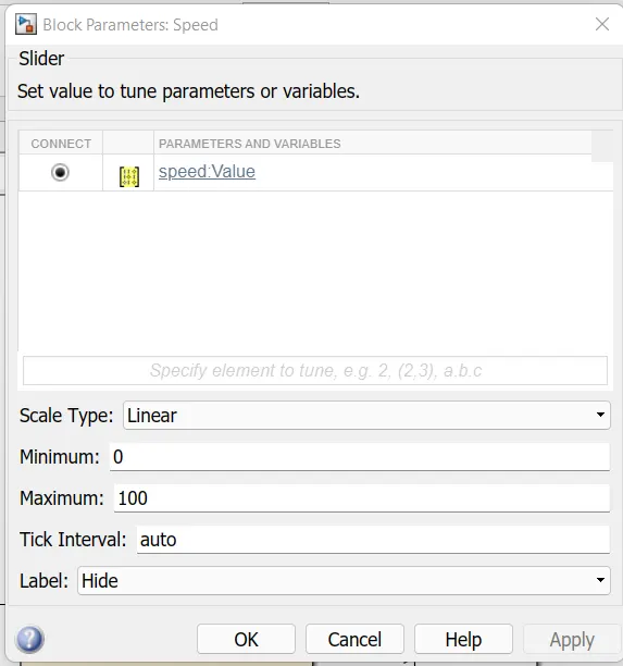
Both Slider block and Constant block is connected to the input, Slider block is used to determine the speed and constant block used to display the speed.
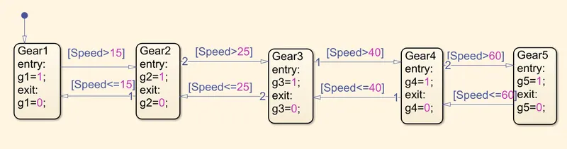
State flow chart or logic used in the system:-
Variable used in logic:-
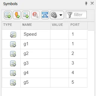
This are the following block used for the setup:-
- State flow chart
- Slider
- Constant
- Display
- Lamp
Model showing gear for speed range:-
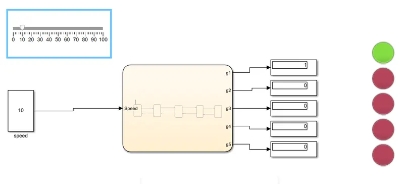
fig(1). Gear 1 for speed range 0 to 15
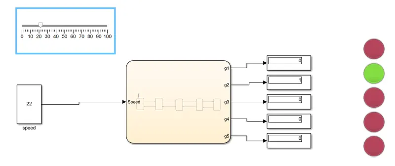
fig(2). Gear 2 for speed range 16 to 25
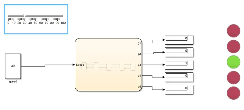
fig(3). Gear 3 for speed range 26 to 40
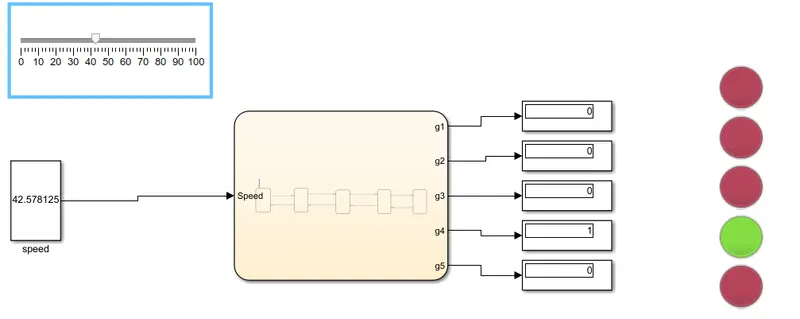
fig(4). Gear 4 for speed range 41 to 60
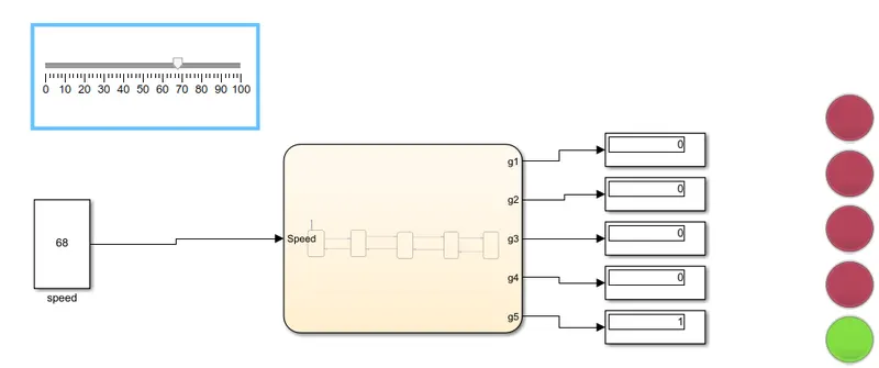
fig(5). Gear 5 for speed range Above 60
A simulink model is created for the gear shift logic and using slider gain the values are obtained.