Project
Ans) All Terrain Vehicle:-
All-Terrain Vehicles (ATV) are among the most useful land vehicles ever invented. Designed to combat the hazards of different kinds of terrain, they can be used in almost every worksite there is. Not only do they make traveling easier for drivers, they are also safe to use when transporting loads or cargo.
Major components used in the simulation :-
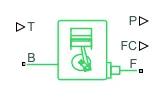
Generic Engine :- The Generic Engine block represents a general internal combustion engine. This block is a suitable generic engine for spark-ignition and diesel. Speed-power and speed-torque parameterizations are provided.
Simple Gear :- The Simple Gear block represents a gearbox that constrains the connected driveline axes of the base gear, B, and the follower gear, F, to corotate with a fixed ratio that you specify.
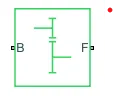
Ports :-
- B-Base Gear OR Driver Gear
- F-Follwer Gear
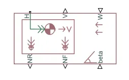
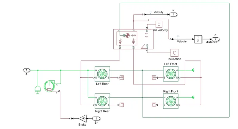
Vehicle Body :- The Vehicle Body block represents a two-axle vehicle body in longitudinal motion. The vehicle can have the same or a different number of wheels on each axle. For example, two wheels on the front axle and one wheel on the rear axle. The vehicle wheels are assumed identical in size. The vehicle can also have a center of gravity (CG) that is at or below the plane of travel.
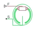
Double Shoe Break:- The Double-Shoe Brake block represents a frictional brake with two pivoted rigid shoes that press against a rotating drum to produce a braking action. The rigid shoes sit inside or outside the rotating drum in a diametrically opposed configuration. A positive actuating force causes the rigid shoes to press against the rotating drum. Viscous and contact friction between the drum and the rigid shoe surfaces cause the rotating drum to decelerate.
Tire:- The Tire (Simple) block represents a simple, no-slip model of a tire that you parameterize by tire radius.The vehicle body is connected to 4 tires each per axle to move the vehicle according to power input to the axle.
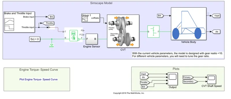
Model:-
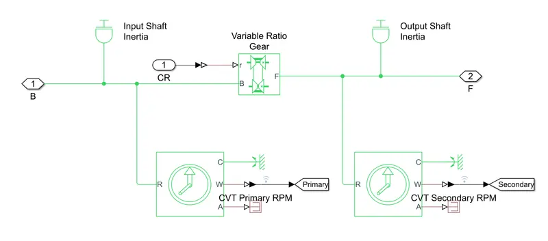
CVT System:-
Vehicle Body:-
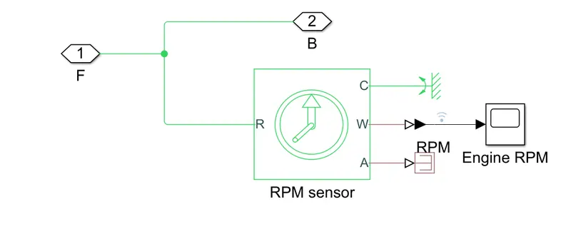
Engine Sensor:- This block measures angular velocity or angle in a mechanical rotational network. The sensor is ideal since it does not account for inertia, friction, delays, energy consumption,so on.
SIMULINK MODEL:-
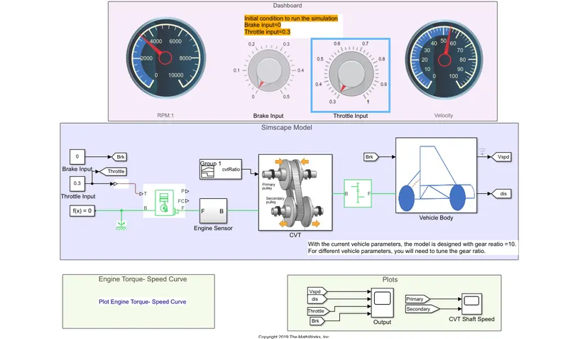
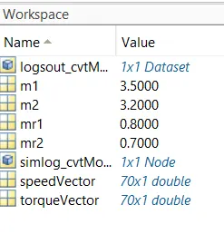
The throttle signal is generated by signal builder block and inputted to the generic engine.The torgue and speed vector are input from the MATLAB work space.
OUTPUT:-
- When the simulation has started the intial throttle input 0.3 and brake input 0 so, output is in below figure.(1)
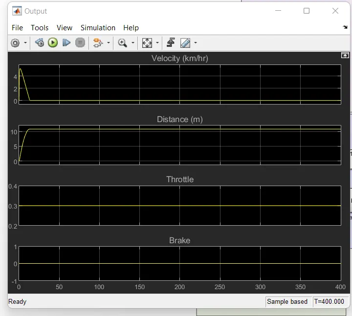
fig.(1)
- When the simulation has started the intial throttle input 0.3 and brake input 0.1. So, output is in below figure.(2).
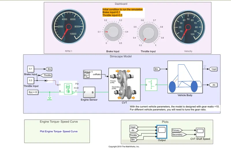
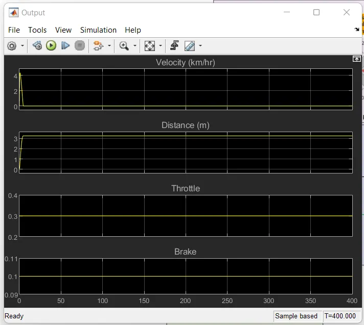
fig.(2)
- When the simulation has started the intial throttle input 0.6 and brake input 0.1. So, output is in below figure.(3).
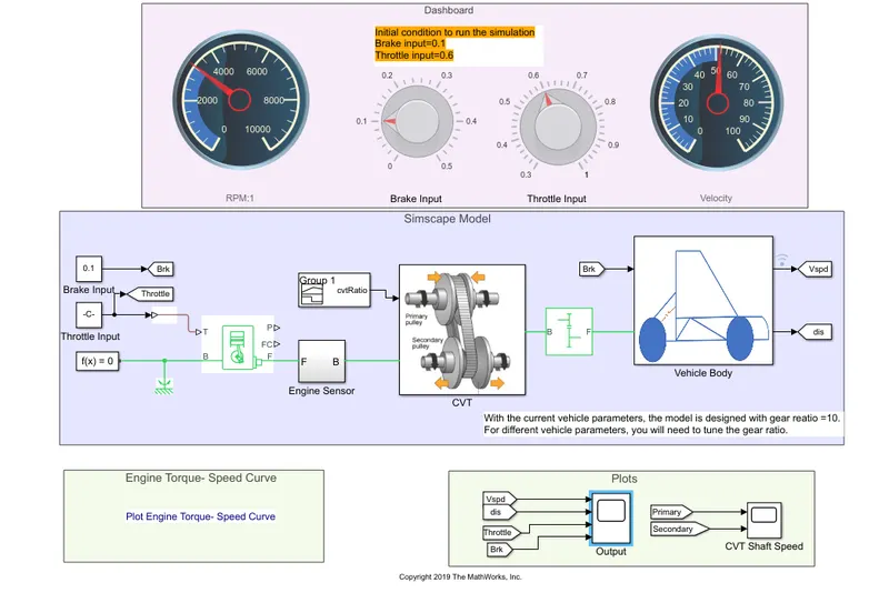
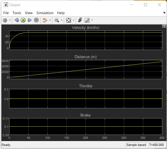
fig.(3)
- In the above fig.(1)graph we can obsrved that when brake is not applied during the drive cycle and the throttle is kept constant at 0.3 then the speed remain is constant.
- In the above fig.(2) graph we can observed that when we set brake input at 0.1 during the drive cycle and the throttle is kept constant at 0.3 then the the speed is decreased.
- In the above fig(3) graph we can observed that when we set brake input at 0.1 and the throttle input at 0.6 then the speed is increased.
From the above all graph we can understand that the throttle is applied (step up) and then kept costant, then braking is applied(step down) and finnaly brake is released so that the engine speed is increased with increase in throttle input.