Week - 4
AIM:
To determine the following challenges using Simulink.
OBJECTIVE:
- Implement control logic of a “washing machine” using Stateflow as per given sequence:
- If the power supply is available, the system gets activated
- If the Water supply is not available, stop the process & indicate through LED
- Soaking time should be 200s followed by Washing time of 100s.
- Then rinsing happens for next 20s & dryer runs for 50s
After all the processes have completed turn on the finished LED
2. Make a Simulink chart for the “Gear shift” logic as per below conditions:
Speed Range(kmph) Gear
0 to 15 1
16 to 25 2
26 to 40 3
41 to 60 4
Above 61 5
Give speed input while the simulation is running & display the gear number.
PROCEDURE FOR CHALLENGE-1:
THEORY:
A washing machine is a machine used to wash various types of clothes without applying any manual effort. It contains a barrel into which the clothes are placed. This barrel is filled with water, and then rotated very quickly to make the water remove dirt from the clothes.
The term is mostly applied to machines that use water as opposed to dry cleaning(which uses alternative cleaning fluids and is performed by specialist businesses) or ultrasonic cleaners. The user adds laundary detergent, which is sold in liquid or powder form, to the wash water.
STEPS FOLLOWED IN WASHING MACHINE:
1.PREWASH:
The prewash indicates filling the drum with a certain water level and mixup with the detergent powder. This options helps to wash out all the strains including the dirt very well from the clothes.
This is possible as we soak the whole clothes placed into the drum.Finally, drain the water.
2.WASHING:
The machine uses agitation which is for mixing both water and detergent in trun moving the clothes all around the drum. The duration taken to complete the wash cycle is depends upon the setings option chosen by user.
Always a heavy load enchances high duration. Small or limited load enchances less duration.
3.RINSING:
This particular cycle is on the flow the soap water is taken from the clothes. And all the fresh water is sprakled to the clothing avaliable in the tub.
This particular option held responsible for taking soapy water out of the washer wihout facing any kind of difficulites. Finally, the agiation with plain water is considerd the last step in the rinsing option.
4.SPINNING:
Spinning is done to dry the entire clothes before getting to the end of the actual wash cycle. And these several washing machines are going to be spin at different speeds.
In turn, the speed of one particular spin is calculated in rpm. This indicates the speed of the spin extracting the whole amount of water from the clothes making it dry very well.
MODEL OF WASHING MACHINE:
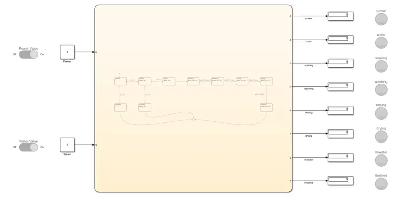
CHART:
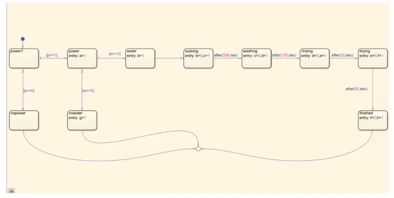
PARAMETERS IN CHART:
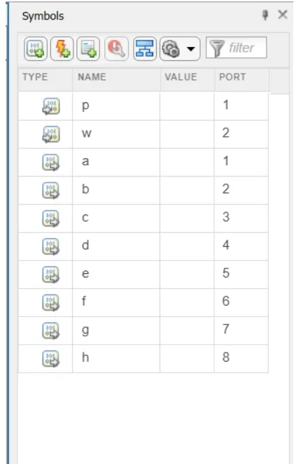
MODEL EXPLANATION:
1. Add two constant blocks from library and name them as power and water.
2.Add slider switches for both constant blocks. Slider switch contains two values. 0 is for OFF condition and 1 is for ON condition.
3.Connect the slider switches with constant blocks of power and water. Slider switches are automatically changed when the values are changed for constant blocks.
4.Chart block is add for the logic that need to be applied for washing machine. Chart block is a state flow logic used in the model.
5.Add states for each process starting from the power. Process takes place when power in ON and OFF conditions. If power is ON the process continues for next step else terminates the whole logic.
6.The process continue when water supply is avaliable. Add state for water with a entry b=1.
7.Join the power state with conditon(w==1). And another state for no power with a entry g=1. Join this with power block with a condition (w==0).
8.When the power and water supply is avaliable washing machine processes takes place. Add state for soaking with an entry b=0,c=1.
9.State is added for washing with entry c=0,d=1. Join with the soaking state with a condition after 200 seconds. This can be given by after 200 seconds.
10.Add state for rinsing with and entry d=0,e=1. Join with the washing state with a condition after 100 seconds. This can be given by after 100 seconds.
11.Add state for drying with and entry e=0,f=1. Join with the rinsing state with a condition after 20 seconds. This can be given by after 20 seconds.
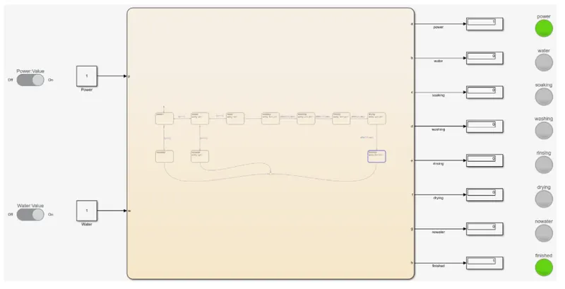
12.The whole process is completed and this should be displayed in LED. Add a state for finished with and entry f=0,h=1. Join with drying state with a condition after 50 seconds. This can be given by after 50 seconds.
13.The states of nopower, nowater and finished are connected to a single point. Opened a parameters for denoting inputs and outputs for the chart.
14.Given input data for p and w. For a,b,c,d,e,f,g,h is given as output data.
15.Connect constant blocks with the inputs ports and give display blocks for all outputs.
16.Named each with a process that takes place and connect all with the lamps providing its value as 1 with green light.
17.Output is displayed.
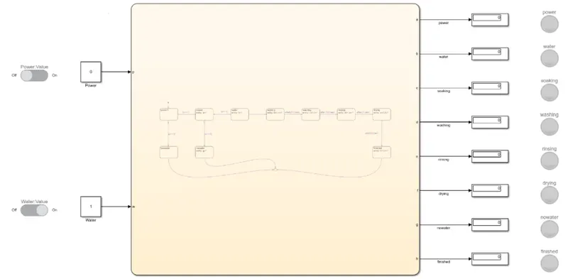
CONDITION-1:
When the power is OFF and water supply is ON. The process does not takes place even tough water supply is avaliable since the power is OFF. The system gets activated when power is avaliable only.
CONDITION-2:
When the power is ON and water supply is OFF. Since the power is avaliable and water supply is unavailable washing does not takes place and "No water lamp" is lights up.
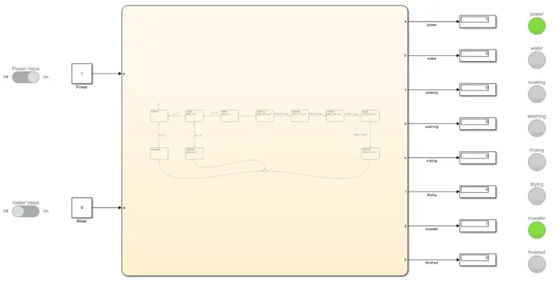
OUTPUTS:
STEP-1:
When the power and water supply is on, soaking takes place for 200 seconds. Soaking lamp lights during this process were,
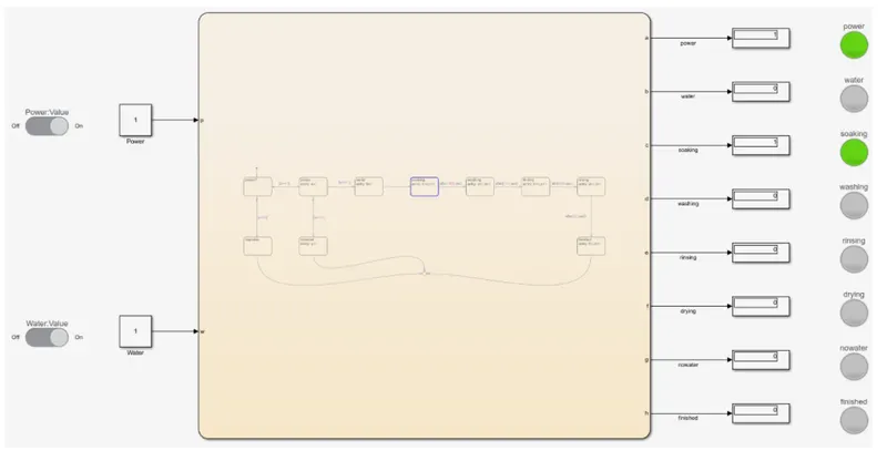
STEP-2:
The next step is washing. It takes place for 100 seconds. Washing lamp lights during this process were,
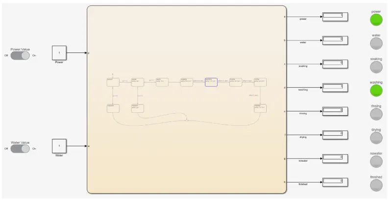
STEP-3:
The next step is rinsing. It takes place for 20 seconds. Rinsing lamp lights during the process were,
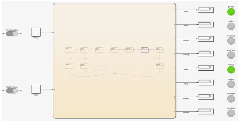
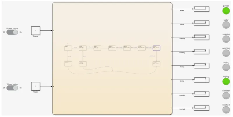
STEP-4:
The next step is drying. It takes place for 50 seconds. Drying lamp lights during the process were,
STEP-5:
After completion of all the process, finished bulb with light up were,
CONCLUSION:
Hence the state flow logic for washing machine is created using simulink.
PROCEDURE FOR CHALLENGE-2:
THEORY:
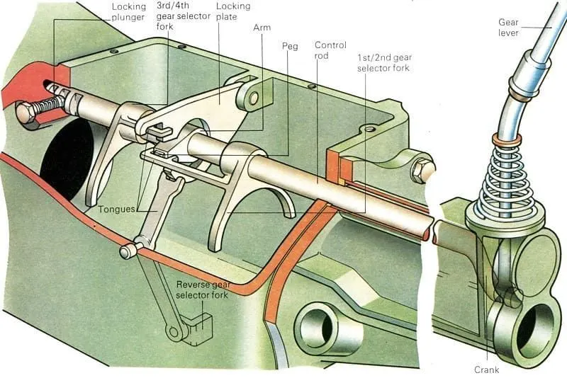
Gear shifting is used for increasing (or) decreasing the speed, torque, power of an engine by higher to lower (or) to lower to higher gears.
A gear shift mechanism for a manual transmission includes a shaft axially movable for selecting shift planes and rotatable for engaging the gears defining the shift planes.
The shaft is held in a reference shift plane by two helical springs. A finger, fixed to the shaft, carries a cam defining detent surfaces engaged by a spring-loaded catch stud.
Shift fork rods support shift forks which have arms formed with grooves extending toward a locking plate that is moved axially along the shaft by the shift finger. The locking plate blocks engagement grooves of the unselected shift forks.
Before the process we wants to follow the below conditions for the model.
Speed Range(kmph) Gear
0 to 15 1
16 to 25 2
26 to 40 3
41 to 60 4
Above 61 5
By doing this we can coded the pattern in the state flow chart which we get to see the Outputs.
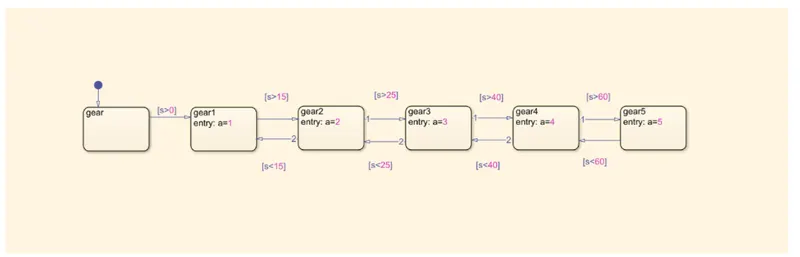
Chart:
MODEL EXPLANATION:
1.Add a constant block and a chart.
2.Creating states for each and every gear that needed to be changed.
3.Creating a state for input taking the values and named it as gear.
4.Creating another state with gear1 and entry as a=1.
5.Join the porcess with previous state with a condition (s>0).
6.Creating a new state second gear as named it as gear2. Since there is a range of speed for each and every gear we use joining in both directions.
7.Gear1 to Gear2 is given by (s>15) and in reverse (s<15).
8.Creating a new state for third gear as named it as Gear3. Gear2 to Gear3 is given by (s>25) and in reverse (s<25).
9.Creating a new state for fourth gear as named it as Gear4. Gear3 to Gear4 is given by (s>40) and in reverse (s<40).
10.Creating a new state for fifth gear as named it as Gear5. Gear4 to Gear5 is given by (s>60) and in reverse (s<60).
11.Given the parameters for s,a. Given the inputs for s and output for a.
12.Adding the slider block to give speed and input. Make a range for 0-150 values for slider.
13.Connect the slider with the constant block.
14.Join the constant block with the chart. Output needed to be known and it is displayed by display block,lamp.
OUPUTS:
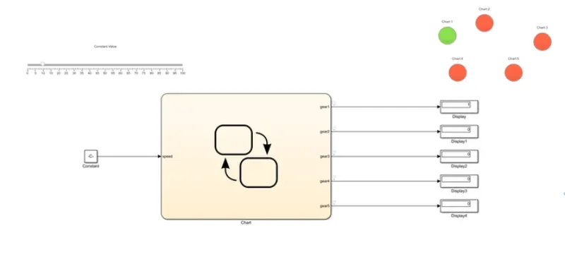
Gear-1: When the value for speed is change in between 0-15, the display shows as,
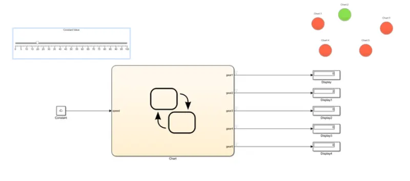
Gear-2: When the value for speed is change in between 16-25, the display shows as,
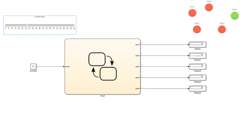
Gear-3: When the value for speed is change in between 26-40, the display shows as,
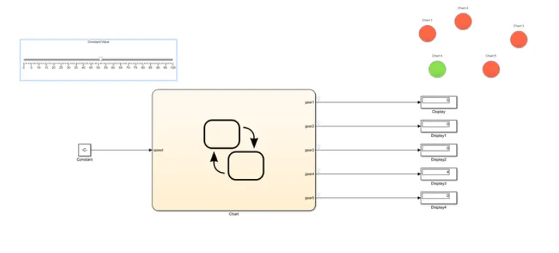
Gear-4: When the values for speed is changed in between 41-60, the display shows,
Gear-5: When the value for speed is changed for above 60+, the display shows,
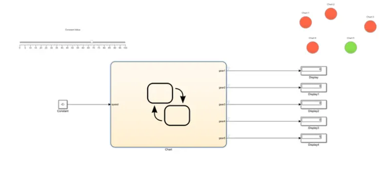
As we can see the lamp is light up is according to the gear it shows and the gear is at the current running according to the speed we selected from slider.
CONCLUSION:
Hence the Gear shifting process using Simulink is programed.
RESULT:
Thus the given challenges are programed sucessfully using Simulink.
REFERENCES:
2.https://www.merriam-webster.com/dictionary/gearshift
3.http://ecoursesonline.iasri.res.in/mod/page/view.php?id=1374