Week - 4
Q.1 Implementation of control logic of a " washing machine " using stateflow
conditions : power supply available -> system activated
water supply not available --> process terminated indicated through LED
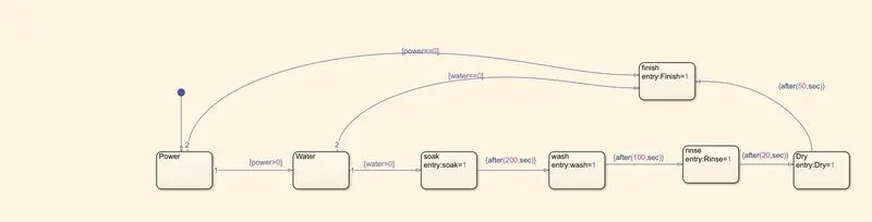
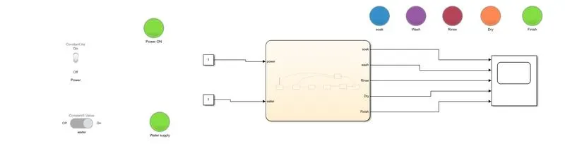
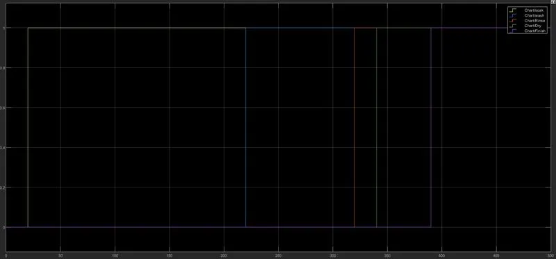
soaking time = 200s, washing time = 100s, rinsing time = 20s, dryer time =50s
Input : power supply, water supply
sequence of operations : power ON -> water supply ON -> soak -> wash -> rinse-> dry-> finish
Output : complete the operation or terminate
simulink state flow:
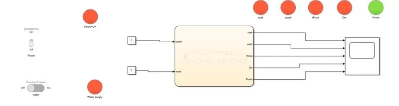
Control logic :
condition 1: Power OFF; Water supply OFF
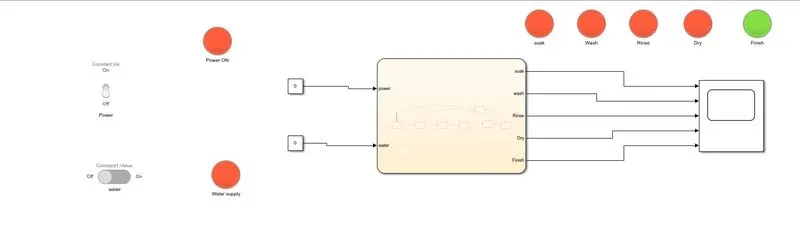
Condition 2: Power ON , Water supply OFF
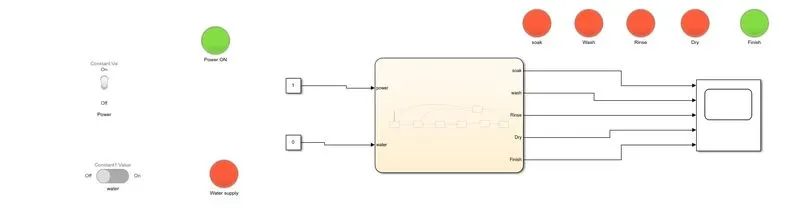
Condition 3 : Power ON, Water supply ON, timer : 500s
Scope:
Q 2: Need to make simulink chart for " Gear shift " logic
| Speed(kmph) | Gear |
| 0-15 | 1 |
| 16 - 25 | 2 |
| 26 - 40 | 3 |
| 41 - 60 | 4 |
| >61 | 5 |
Input : Speed ; output : Gear number display
step 1
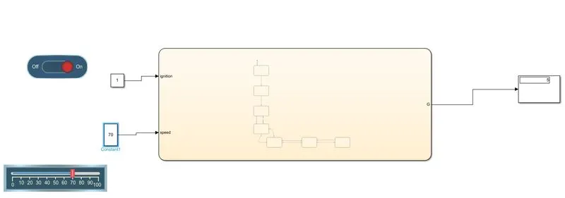
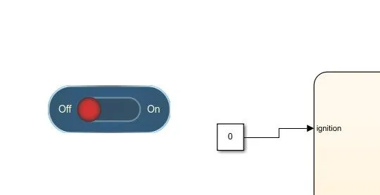
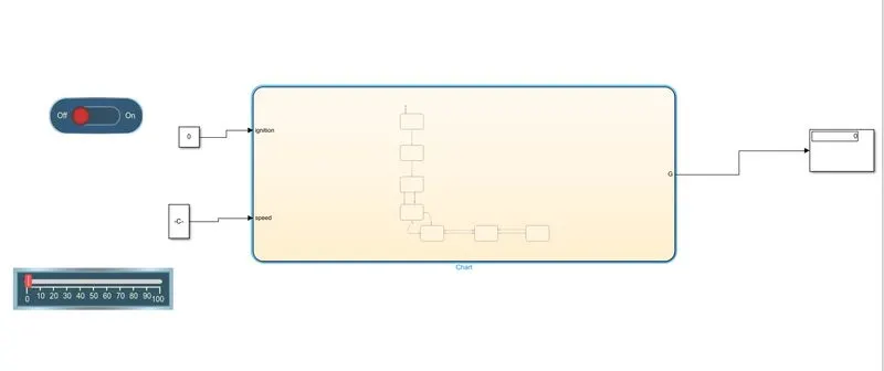
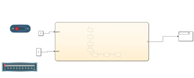
1) Take the input switch control for Ignition through slider switch from dashboard menu available at library browser
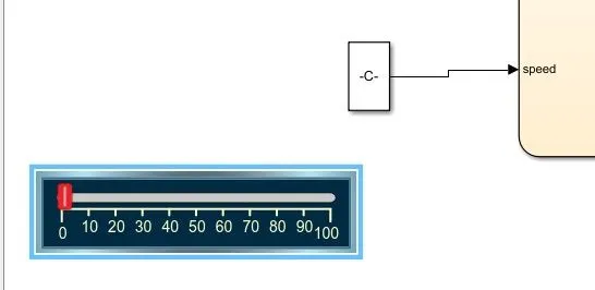
2) Take the input switch for speed control as horizontal slider from dashboard menu at library browser
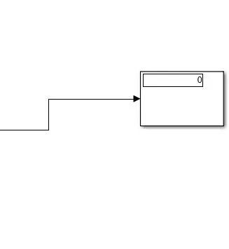
3)Out put gear is displayed through display block
4) state flow chart for gear shift mechanism
5)Control logic for gear shift mechanism
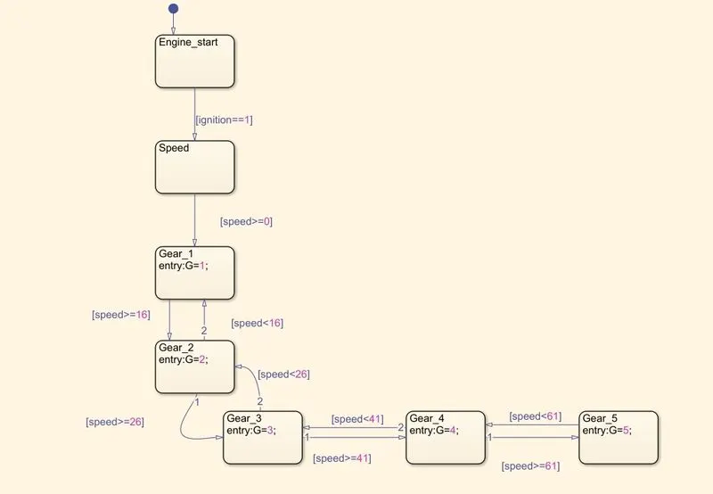
6)case -i: IGN=OFF, Speed =0,Geardisplay output=0;
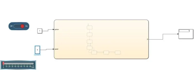
case- ii: IGN =ON,speed =0, gear display =1
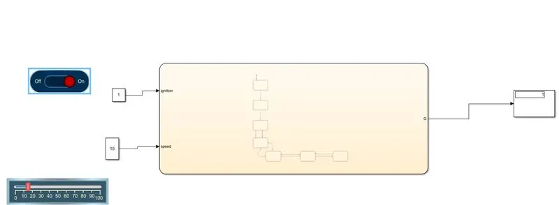
case -iii: IGN = ON, Speed =15, gear display=1
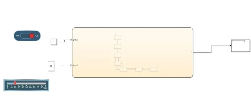
Case- iV: IGN =ON, Speed = 20, gear display =2
Case -V: IGN =ON, speed =40, gear display = 3
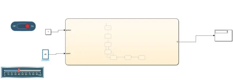
Case-Vi: IGN = ON , speed = 50 , gear display = 4
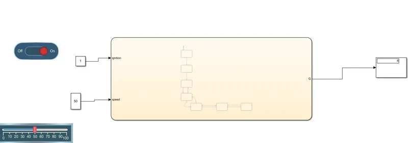
Case -Vii: IGN =ON , speed = 70 , Gear display = 5