Week -2
Q.1 Simulink model for door bell using a solenoid
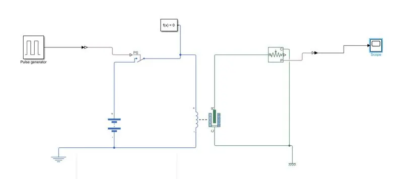
To execute this system we have used the below blocks
Pulse generator : As per the requirement the plunger has to move for 2 seconds and stop this will be possible only using
pulse generator and it is connected to PS switch using simulink - PS converter
Solenoid : it is connected to the idea transitional motion sensor to sense the position of the plunger
Battery : It is connected to provide the current to the circuit through the PS switch based on its ON/OFF condition from pulse generator
Ideal Transitional motion sensor : It is used to identify the position of the plunger when solenoid converts from electrical energy to mechanical energy which is surrounded around the plunger which makes it move in transational direction
Solver : It is used to solve the electrical system and identify the type of system(continuous or discrete)
The circuit need to be grounded properly by using Electrical reference and mechanical translational reference
OUTPUT :
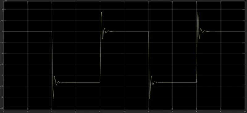
from the above graph we can identify that plunger moves from initial position to 3.1mm and takes delay time of 2secs and then rings the bell by hititng the bell and the reaches to 0 mm takes again delay time of 2secs between 2 to 4 sec s
Q 2. Use thermistor to sense the temperature of a heater & turn on / off the fan based the temparature range ginev below
Temperature source : 20 deg from 0 to 10 secs , 27 deg from 10 to 30 secs , 23 deg from 30 to 50 secs
Fan ON/OFF condition : > 25deg Fan ON ; otherwise it should be OFF
To simulate this we use different below blocks
Thermistor: Thermistor means Thermal + resistance . It is a type of resistor whose resistance is dependent on temperature.
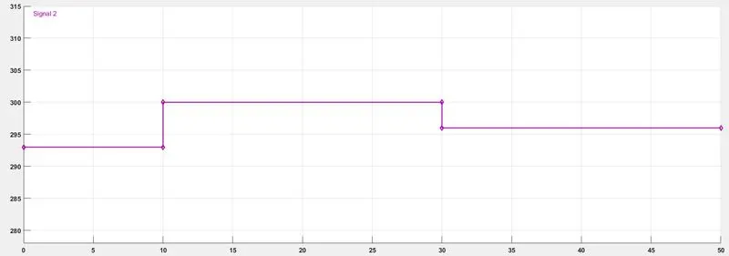
Signal builder : By using this we can generate the desired input signal by taking temperature and time as co ordinates
signal values : 0 -10 secs 20 degs (293 K), 10 -30 secs 27 deg( 300 K), 30 -50 secs 23 deg (296K)
Controlled temperature source : It is connected between signal generator and the thermistor to understand the input from the signal generator and thermal reference is added to maintain the potential difference
Simulink - PS converter is used from signal generator to control temperature generator
Battery is connected to run the circuit
Solver is connected to electrical system to identify the type if the system
Voltage sensor is connected across the resistor to measure the threshold voltage across the circuit
Switch : in order to simulate the FAN condition we use a switch provided with a threshold value ( if below the value its OFF, ON it is above the value )
Constants : we use if else logic to simulte the FAN condition , In order to identify the True or False conditions we use constant blocks
Scope block is used to get the results ( output)
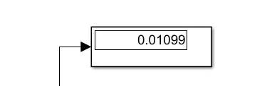
Display block used to display calculated threshold value for the switch
Output :
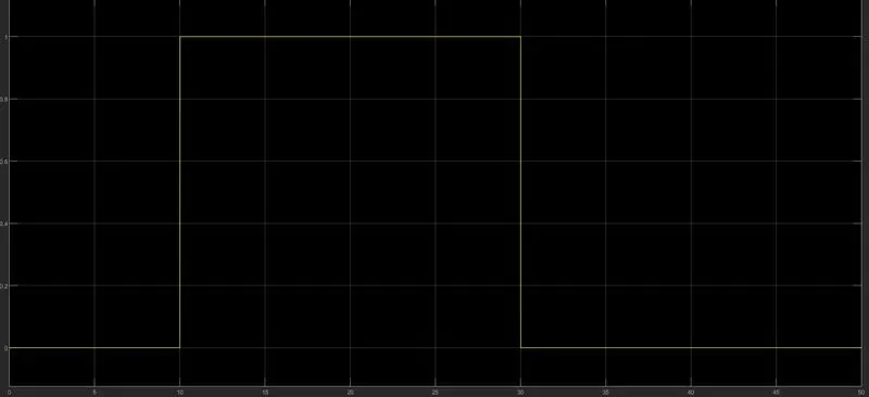
From the graph we can see that during 0-10 sec temp value is 20deg(293K ) fan is OFF , 10 -30 secs temp value is 27 deg (300K) Fan is ON , 30 -50 sec temp is 23 deg (296K) Fan is OFF