Week - 4
1.Implement control logic of a “washing machine” using Stateflow as per given sequence:
- If the power supply is available, the system gets activated
- If the Water supply is not available, stop the process & indicate through LED
- Soaking time should be 200s followed by Washing time of 100s.
- Then rinsing happens for next 20s & dryer runs for 50s
all the processes have completed turn on the finished LED
AIM :
1. To Implement control logic of a “washing machine” using Stateflow as per given sequence.
2. Make a Simulink chart for the “Gear shift” logic as per given conditions.
OBJECTIVE :
1. In Simulink, Implement the Control Logic of a Washing Machine using State Flow as per given conditions.
- If the power supply is available, the system gets activated
- If the Water supply is not available, stop the process & indicate through LED
- Soaking time should be 200s followed by Washing time of 100s.
- Then rinsing happens for next 20s & dryer runs for 50s
Create a model and Operate the model logic system and Display the Output of the results by using Lamp Indicator.
PROCEDURE :
To create the required model we will be using the chart block in Simulink in which we will be using Stateflow for implementing the given control logic. The required theory has been explained below.
Simulink blocks required for this model is as follows-
| 1. Lamp - |  |
This displays a color for the respective outputs. These blocks will be used to show that each process has been completed. |
|
3. Slider Switch - |
 |
The Slider Switch block toggles the value of the connected block parameter between two values during simulation. For example, you can connect the Slider Switch block to a Switch block in your model and change its state during simulation. Use the Slider Switch block with other Dashboard blocks to create an interactive dashboard for your model. |
|
4. Constant - |
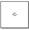 |
This block will be connected with the toggle and rocker switches and acts as an input to the model |
| 5. Display - | 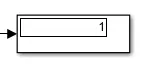 |
These blocks will display the outputs from the state flow. |
PROCEDURE :
First and foremost we need to build stateflow chart and define the given conditions with help of state actions and transitions so that we can create a input and output port for the model
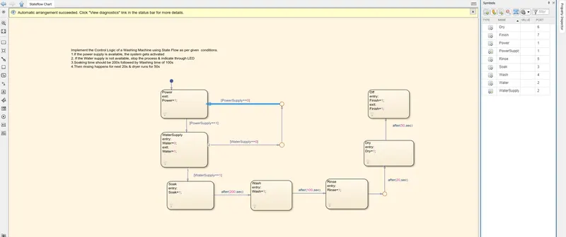
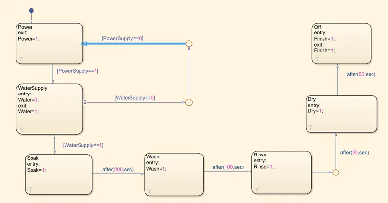
so,we first drag a default state block and with tile as POWER since power supply is the initial state and we will add transition conditions that if [PowerSupply==1] we will proceed to next state otherise if [PowerSupply==0] the state action revert backs to the default state.
in the secon state we will "watersupply" state in which if the powersupply is equals 1 it will turn on water supply otherwise the state goes to deafult.in the next state we will continue with transition condition i.e., [waterSupply==1] by connected to SOAK state.
here the state is defined with a specific time period of 200seconds and after that a new state with time of additional 100seconds which is an action time for WASH state.so it sums up that at the end of 300sec these states i.e, watersupply-soak-wash has been completed.
in the following state we will be adding RINSE with run time for 20 sec after that it goes to DRY state with 50sec duration then finally the last State that is OFF which finishes the one cycle time i.e.,a total of 370sec washing machine time in which SOAK-WASH-RINSE-DRY has been implemented.
Finall we need to define the correct data type for the state and action names we have assigned and sort out the port values so that we can see the output in a definite manner.
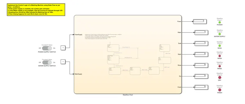
after completing the stateflow chart we will come back to the simulink workspace and connect the input to POWER SUPPLY SWITCH & WATER SUPPLY SWITCH by linking through constant block and output ports to the constant block wich are defined with lamps where he Lamp block displays a color to indicate the value of the input signal here we have defined 1 and 0 as TURNED ON & TURNED OFF with GREEN & RED LIGHT indications.
SIMULINK model :
STATEFLOW model :
RESULTS :
Condition 1 : When there is no power and no water.
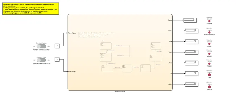
As there is no water and power the signal is displayed red and the further opeation did no take place.
Condition 2 : When there is power and water.
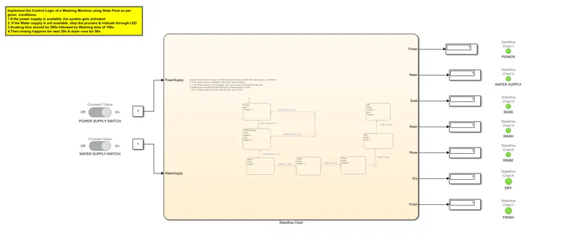
As there was water and power is supplied, the display became green, condition got cleared and all the above process proceeded and got completed.
Condition 3 : When there is power and no water.
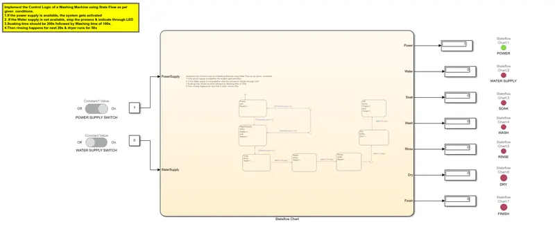
when there is power supply but the water supply is not available it wont proceed to further operations and the other state indicators become red.
2. Make a Simulink chart for the “Gear shift” logic as per below conditions:
Speed Range(kmph) Gear
0 to 15 1
16 to 25 2
26 to 40 3
41 to 60 4
Above 61 5
Give speed input while the simulation is running & display the gear number.
AIM :
Make a Simulink chart for the “Gear shift” logic as per given conditions.
OBJECTIVE :
Create a model for Gear Shifting logic as per given conditions.
Speed Range(kmph) Gear
0 to 15 1
16 to 25 2
26 to 40 3
41 to 60 4
Above 61 5
Give the Speed input while simulation is running and Display the gear number
To create the required model we will be using the chart block in Simulink in which we will be using Stateflow for implementing the given control logic. The required theory has been explained below.
Simulink blocks required for this model is as follows-
PROCEDURE :
| 1. Lamp - | |
This displays a color for the respective outputs. These blocks will be used to show that each process has been completed. |
|
2. Constant - |
|
This block will be connected with the toggle and rocker switches and acts as an input to the model |
|
3. Slider block |
 |
The Slider block tunes the value of the connected block parameter during simulation. For example, you can connect the Slider block to a Gain block in your model and adjust its value during simulation. You can modify the range of the Slider block's scale to fit your data. Use the Slider block with other Dashboard blocks to create an interactive dashboard to control your model. |
| 5. Display - | |
These blocks will display the outputs from the state flow. |
PROCEDURE :
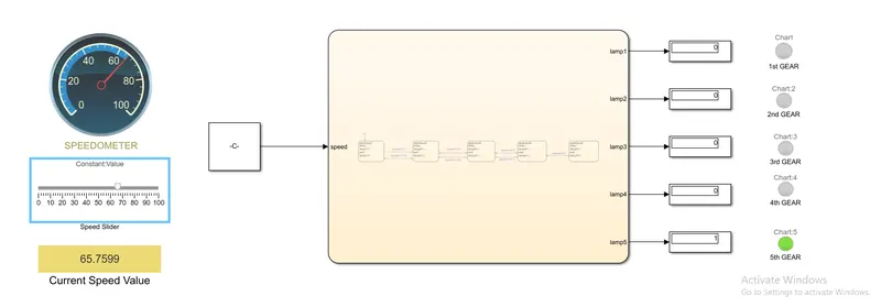
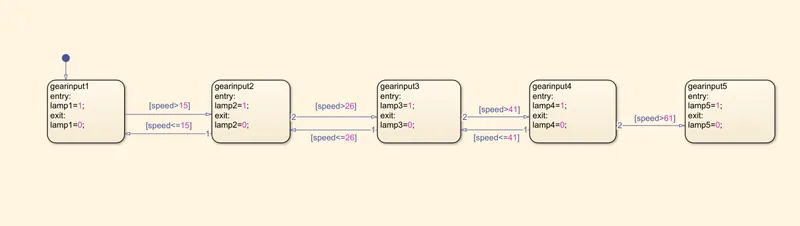
first, we have created first state Gearinput1 and in this, we have given a condition such that if input speed>15 then the gear got shifted to second gear. That means, if speed<=15 condition satisfied then the car remains in the first gear only.
- When the speed>15 condition got satisfied then the car got shifted to second gear(gearinput2 state). Then the car remains in the second gear until speed goes above 25 unit.
- When speed>25 condition got satisfied then the car shifted to third state gearinput3. Further, if speed falls to 25 and below 25 unit, the car got again shifted to second gear.
- Furthermore, if speed>40 condition got satisfied then the car shifted to fourth state gearinput4. Further, if speed falls to 40 and below 40 unit, the car got again shifted to third gear.
- Also,if speed>60 condition got satisfied then the car shifted to fifth state gearinput5. Further, if speed falls to 60 and below 60 unit, the car got again shifted to fourth gear.
- If the speed remains to be higher/greater than 60 unit then the car will remain in fifth gear only untill there is any drop in speed of the car.
For input, we use constant block, From Dashboard, we use slider gain block and set the lower limit to 0 and higher limit to 100.This is the speed limit.
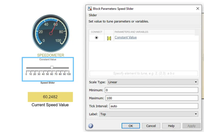
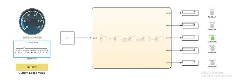
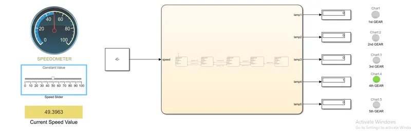
The timer for simulation is set to infinite(inf). The constant is connected to slider block and the constant output is an input to chart. The lamps are used to display the gear which is operational. The lamps are connected to its respective result. When any value is 1. That is if the condition is true in stateflow and the system is in particular gear, it will display its result and display that lamp. All other lamp are off as its value is 0.
SIMULINK model :
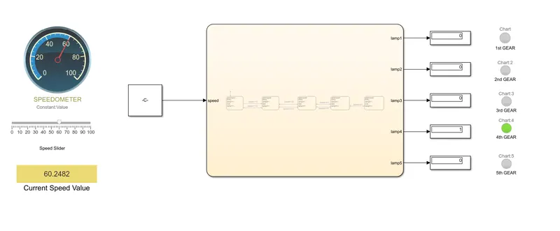
STATEFLOW model :
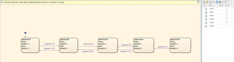
RESULT :
in the video below we have given speed input while the simulation is running & we can see the speed value and its gear number with lamp indicator instantly.
GEAR 1 :
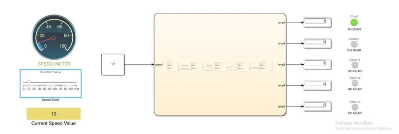
GEAR 2 :
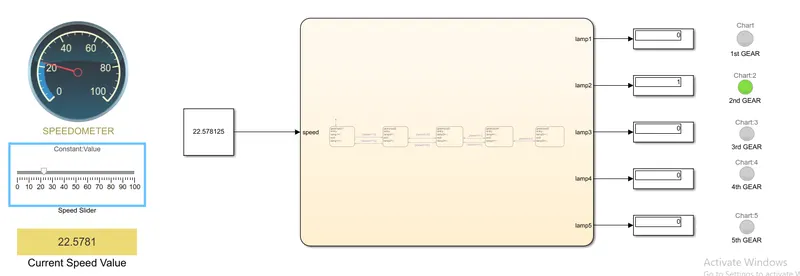
GEAR 3 :
GEAR 4 :
GEAR 5 :