Week 4 - 2D Meshing for Sheet Metal
Week - 4 – 2D Meshing for Sheet Metal
CCD ASSEMBLY
Report
Aim
For the given CCB CAD model,
- To check for the geometrical errors
- take the mid surface
- mesh the Surfaces with the given 2D element Quality criteria.
Quality criteria
|
Sl. No |
Quality Criteria |
Value |
|
1 |
Target/Average length |
5 |
|
2 |
Minimum Length |
3 |
|
3 |
Maximum Length |
7 |
|
4 |
Aspect |
3 |
|
5 |
Warpage |
15 |
|
6 |
Skewness |
45 |
|
7 |
Jacobian |
0.7 |
|
8 |
Minimum Quad Angle |
45 |
|
9 |
Maximum Quad Angle |
135 |
|
10 |
Minimum Tria Angle |
30 |
|
11 |
Maximum Tria Angle |
120 |
|
10 |
Tria Percentage |
15 |
Procedure
- Open the cad model in ANSA V23.0.0 using the file>open option.
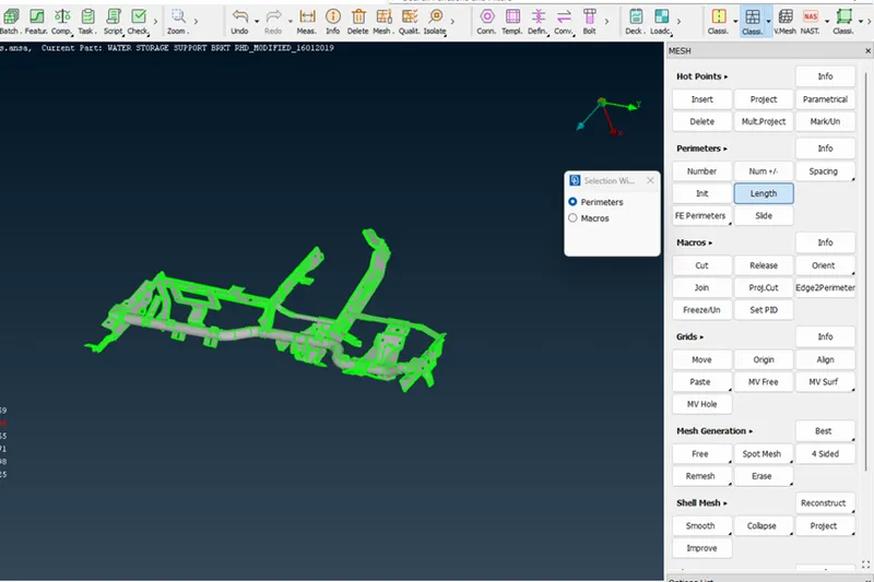
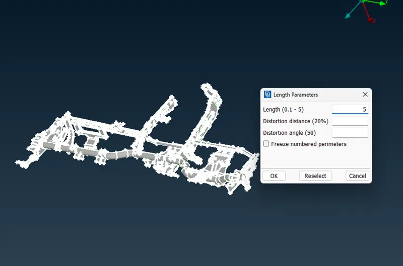
- Go for Length option from the mesh module to find out the actual geometry of a model.
Box select the model and enter the value for perimeter as 5.
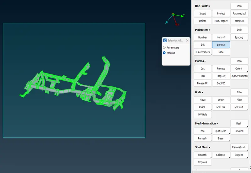
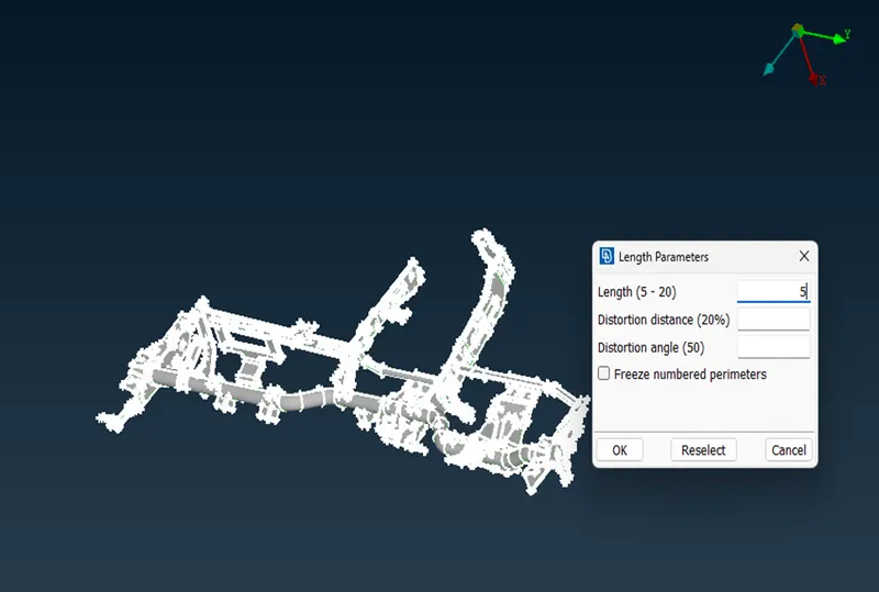
Box select the model and enter the value for macro as 5
3. Perform topo on it, as the model is too distorted after importing from different software
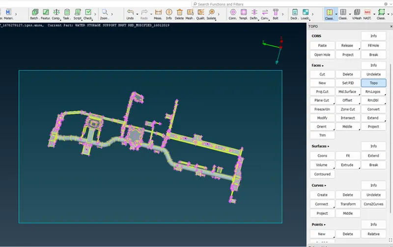
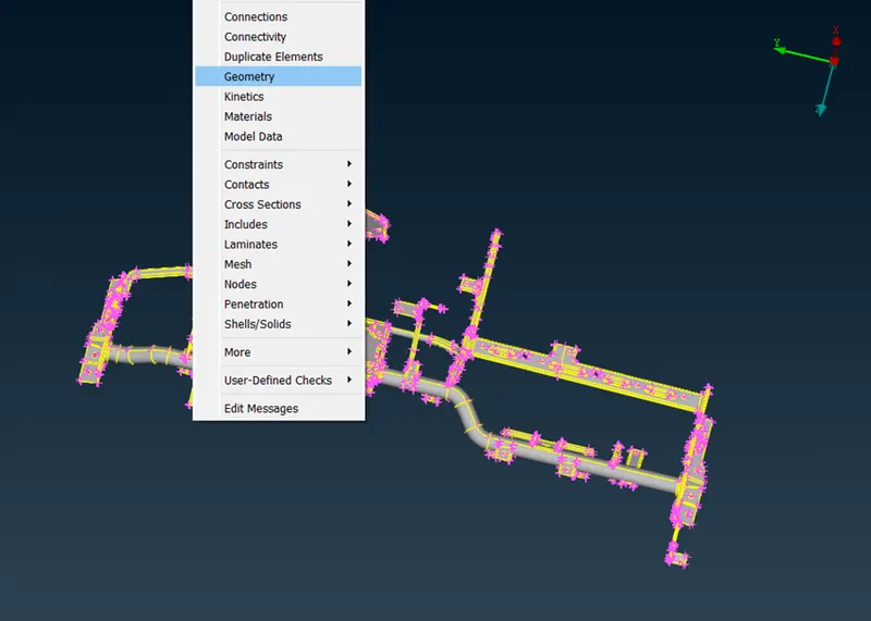
4. Geometry Check and execute
5. Select all the errors and perform
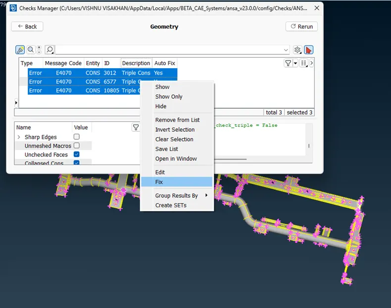
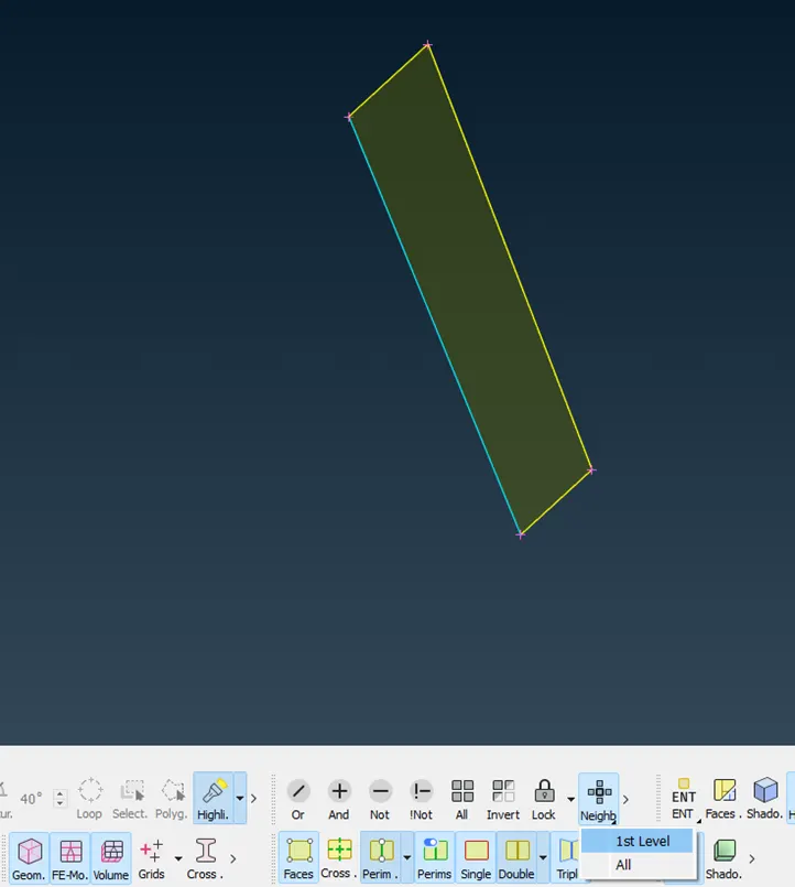
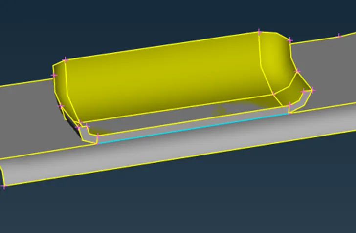
6. The model was later checked for geometrical errors using Checks for Geometry and have one error. Right click and hit show only to see the error.
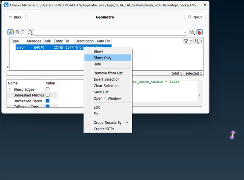
7. Select Neighb 1st level to see the adjacent faces.
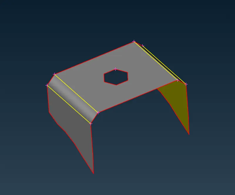
8. Mid-surface generation
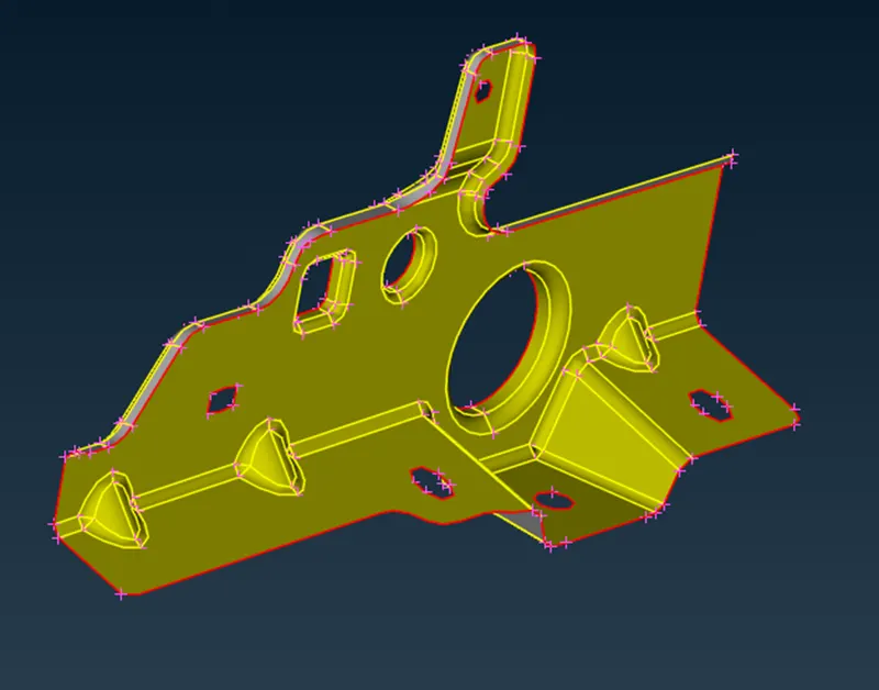
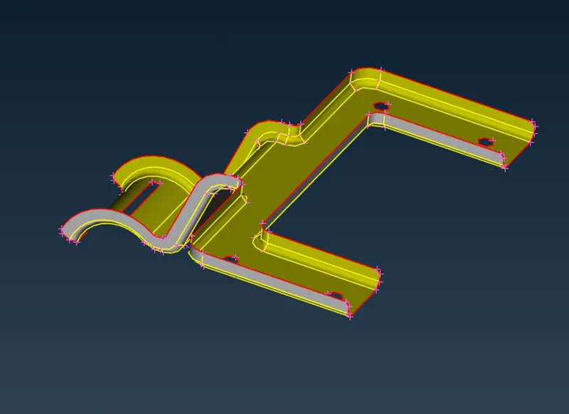
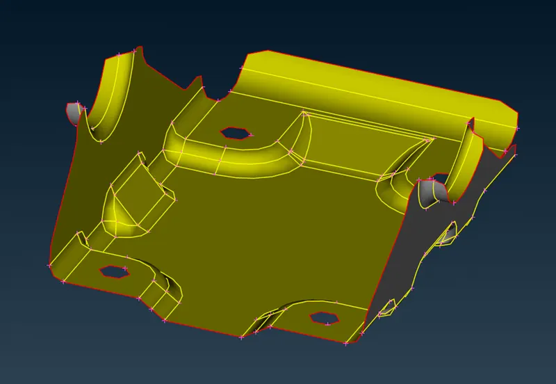
9. Complete Mid-surfaced model
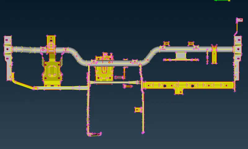
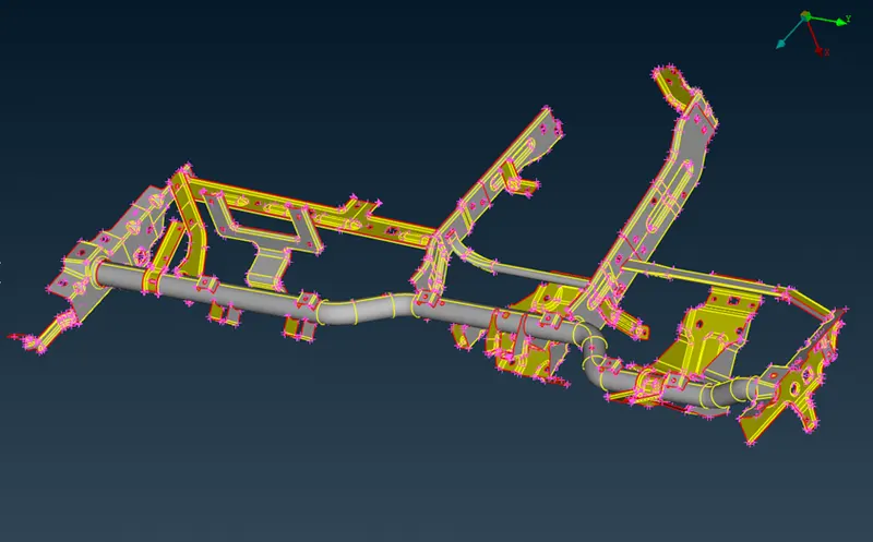
10. After taking mid-surface to perform geometry check and uncheck single con.
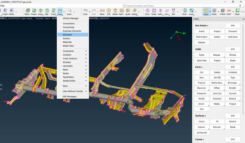
11. Now that all the errors have been cleared, we can start generating the mid-surface for each of the components of the assembly. Measure the thickness at all regions for placing the mid-surface at the correct distance. The components are found to be of uniform thickness; thus, we can use the skin option also to generate the mid-surfaces automatically.
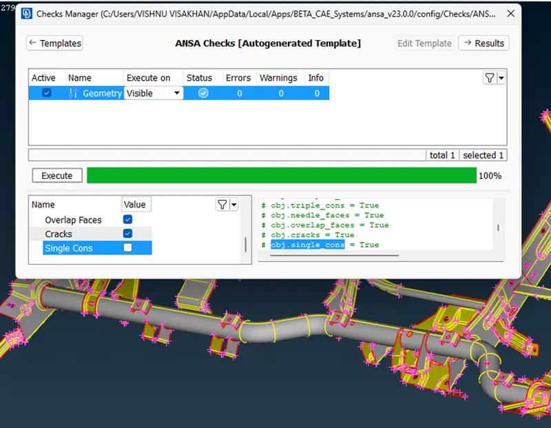
12. Before starting meshing perform Classic Topo-Faces-Orient.
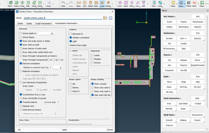
13. After generating all the mid-surfaces, the next step is meshing. Prior to meshing, define the required quality criteria.
Quality criteria
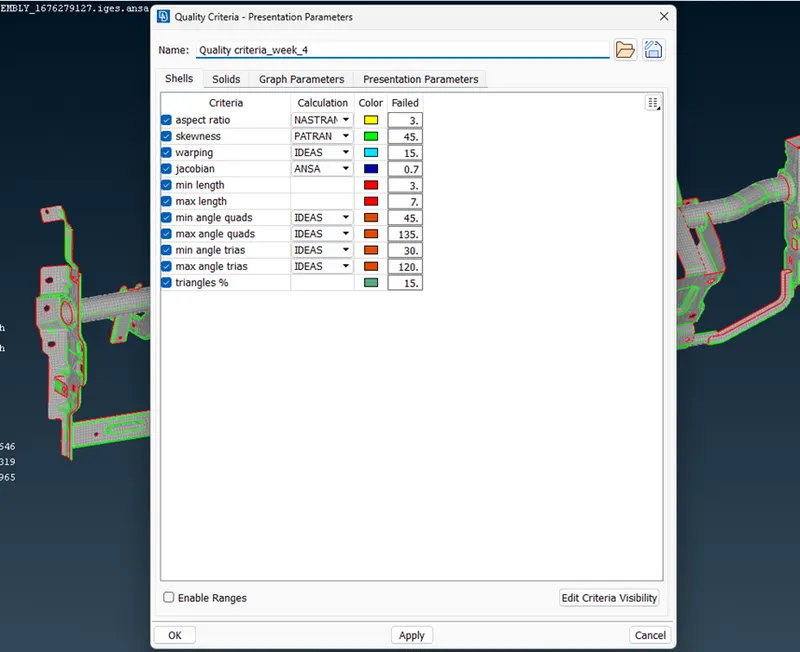
Mesh Parameters
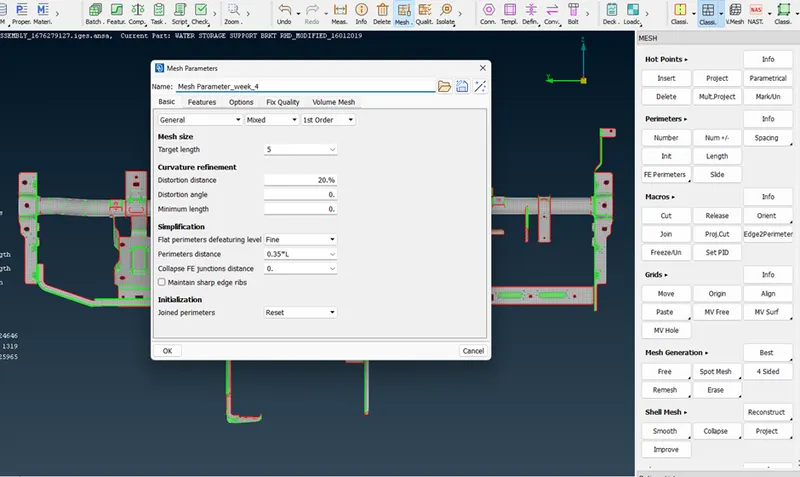
14. Meshing
Mesh all the mid-surfaces to qualify the quality criteria and confirm the same by viewing the model in hidden mode. Make sure to create a zone cut around all bolt holes. Do not forget to apply thickness.
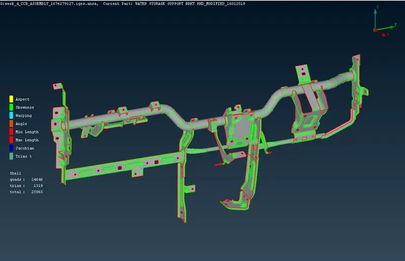
15. Assigning thickness
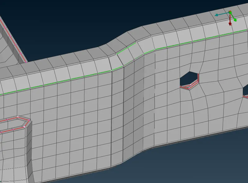
Final Mesh Model
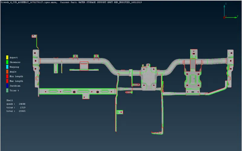
Thickness Applied Model
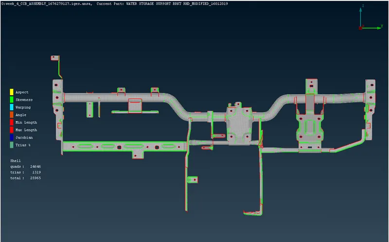
Result:
- The geometry was cleaned, and the mid-surface was generated.
- The mid-surfaces meshed, and thickness was applied.