Week 4 - 2D Meshing for Sheet Metal
Optimized 2D Meshing in CCB model, a sheet Metal Assembly
Problem Description:
In this exercise, a CCB model, a sheet metal component assembly having 34 sub parts is going to perform the Meshing operation after completing Geometric cleanup, defeaturing, topo operations. The main aim of this week-4 challenge is to reduce the time taken 2D sheet metal meshing component without deviating quality criteria
Introduction:
This sheet metal CCB model assembly consists of 34 parts and only one Component has been made symmetrical with respect to XZ plane. In this assembly there are 4 different thickness has been observed and are listed below,
|
S.NO |
Average Component Thickness |
No of Components |
|
1 |
1.2 mm thk |
6 |
|
2 |
1.6 mm thk |
24 |
|
3 |
2 mm thk |
1 |
|
4 |
2.5 mm thk |
3 |
The following steps has been done for the mesh extraction
- Geometry clean up
- Mid Surface Extraction
- Mesh creation within specified quality criteria.
1) Geometry Cleanup:
Geometrical disturbances link cracks, needle faces, smaller features etc should be removed initially to achieve the desired results. Geometric cleanups are done by following procedure.
- Geometric check
- Defeaturing
- Increasing Cons Resolutions
1.1) Geometric check:
Initially the model file (IGES format) has been opened in the ANSA. Because of file importing all cons has not been associated with adjacent cons. So it has been reflected as single cons.
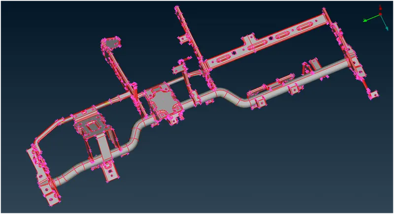
(Image-1: Geometry Check without topo)
In order to make error free geometry, the following steps are incorporated,
Step-1: Since all cons are not connected with adjacent cons, topo operation has been performed in a single stretch to save time.
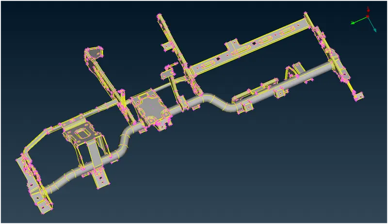
(Image-2: Single stretch topo operation)
Step-2: Cracks, needle face, geometric overlaps, triple cons, collapsed cons etc are identified by using Geometry check option. This option avails under Tools -> Checks -> Geometry.
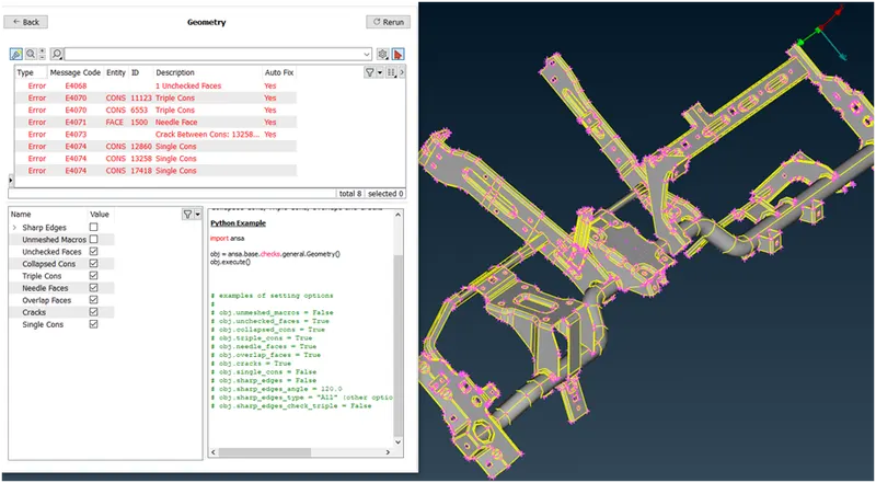
(Image-3: Geometry error)
Step-3: After performing geometric checks, these geometrical errors (before Mid-surface Extraction) have been removed automatically, using fix option.
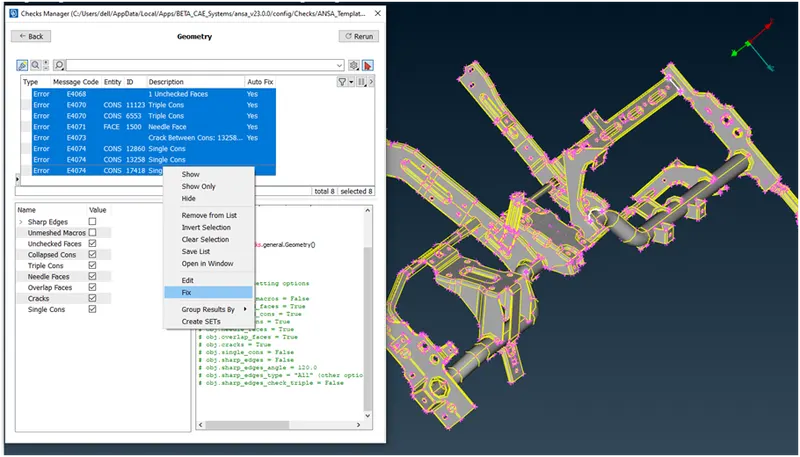
(Image-4: Error Fixing)
Alternately we can fix these errors manually by
- Deleting needle faces
- Releasing triple cons,
- Manual topo operations on cracks.
Further Geometrical clean ups should be done by performing the following operations,
1.2) Defeaturing:
Smaller features with size less than MINIMUM ELEMENT sizes should be removed to avoid quality failures. In this Exercise features (like fillet, chamfer, holes etc) with size less than 3mm should be removed.
1.3) Increasing Cons Resolutions:
All parts resolutions are fine tuned with single stretch by performing this operations. Under classic mesh option click perimeter -> length -> specify length 5mm (average element size). Entire surface cons resolution will be adjusted accordingly.
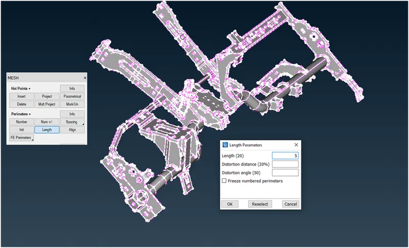
(Image-5: Cons Resolution adjustment)
Then geometric orientation has been adjusted by displaying grey color at top faces and yellow color to bottom faces
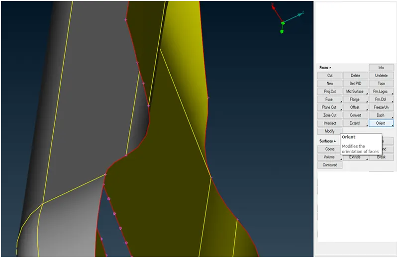
(Image-6: Orientation check)
Since all these operations are done before Mid-surface Extraction, we have to cross verify the component after Mid-surface extraction. Because of adjacent B-spline surface, there may be any crack propagations and needle faces formations in few surfaces. So these should be removed
2) Mid Surface Extraction:
Since this exercise comprises of sheet metal components, thickness is very less as compared to other dimensions. So we are neglecting thickness by creating Mid-surface and considering all components as 2D parts to reduce meshing time.
Why Mid surface?
- Accuracy of end results can matches with solid mesh,
- Reduces geometric preparation time,
- Reduces Simulation time,
- Faster and accurate results achievable
- Since mid surface lies in neutral axis(Medial Axis) of the sheet metal component, additional unwanted stress build up because of geometry has been reduced. Hence the original 2D object has been recovered with the help of Mid surface at medial axis.
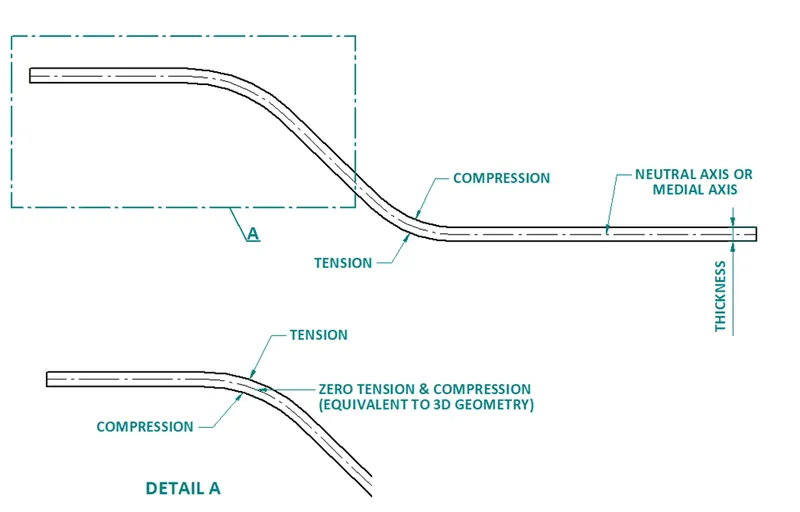
(Image-7: Mid surface Advantage)
After geometric clean operation Mid-Surface has to be extracted with the help of auto mid surface or using offset option.
- If auto mid surface is used, we have to assign appropriate color coding to appropriate face.
Red or green Color: Inner or outer Surface
Blue Color: Thickness side
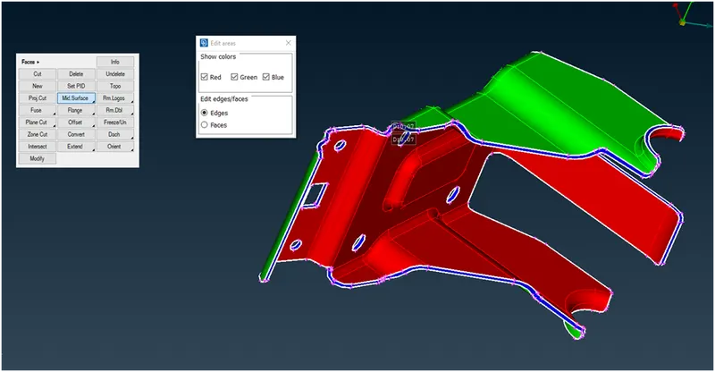
(Image-8: Mid surface Extraction)
- If offset option preferred we have to select all outer surfaces or all inner surfaces and 0.5 times of thickness has to be offset to extract the mid-surface. Here 4 types of thickness are available and its offset value are shown below,
|
S.NO |
Average Component Thickness |
Offset value to extract mid surface |
|
1 |
1.2 mm thk |
0.6 mm |
|
2 |
1.6 mm thk |
0.8 mm |
|
3 |
2 mm thk |
1 mm |
|
4 |
2.5 mm thk |
1.25 mm |
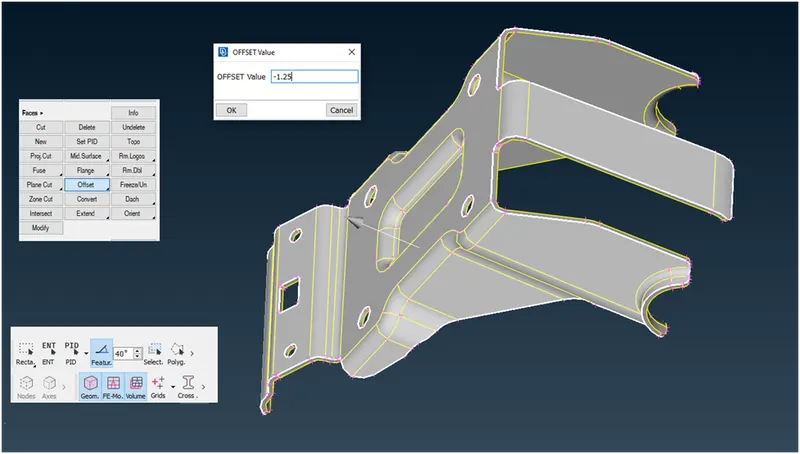
(Image-9: Mid surface Extraction via offset)
- In-order to reduce meshing time of symmetric parts, Dbl under Faces option option has been used to identify the symmetric parts,
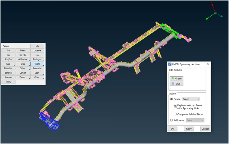
(Image-10: Symmetrical part isolation)
Here only one part (COMPONENT 25 & COMPONENT 80) is symmetric and rests of the part are different
- Transform options has been used to create mirror operation to save time
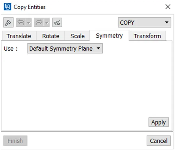
(Image-11: Performing Symmetrical operation)
- After Mid-surface extraction, make sure all features like holes, slots etc should have even number of nodes with the help of number menu under Also unwanted hot points should be deleted.
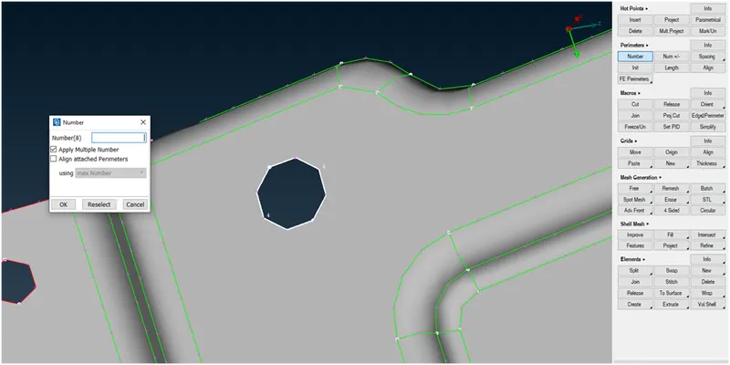
(Image-12: Nodes adjustment)
- After adjusting the holes parallel to one edge with the help of slide menu under perimeter in order to get smooth mesh flow, holes nodes are marked in-order to avoid nodes collapsing.
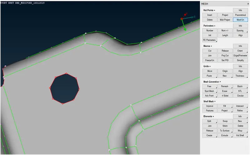
(Image-13: Nodes alignment)
Finally the Meshing operations are going to carry after performing these steps.
3) Mesh creation within specified quality criteria:
3.1) Meshing:
The quality criteria and mesh parameter for this exercise are shown below,
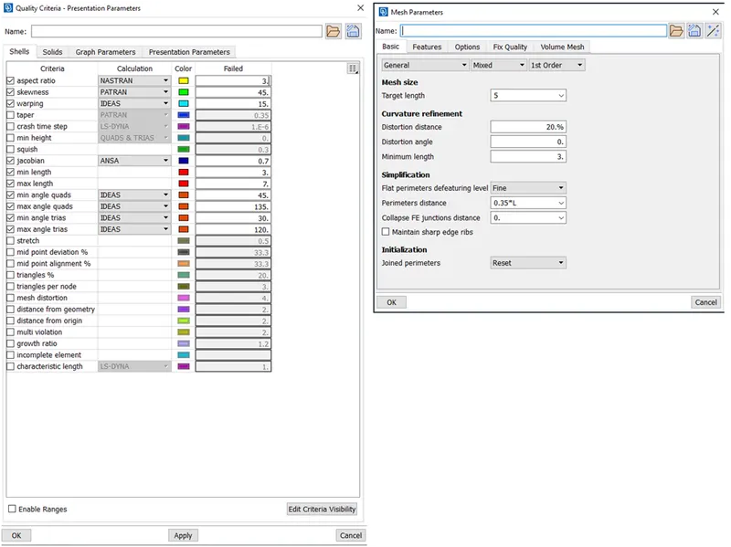
(Image-14: Quality criteria)
- Using Cut/ Join/ proj cut Menu under Macros cons has been removed or added based on requirement. Also unwanted hot points have been removed by using Delete menu under hot points.
- Free option under Mesh generation used to generate free mesh.
- Elements have been splitted and joined at some areas to reduce trias.
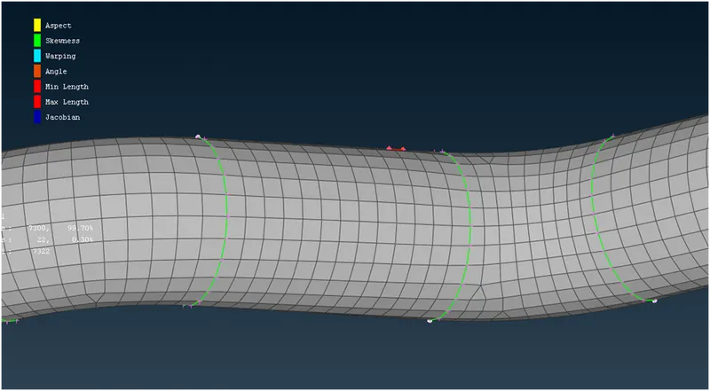
(Image-15: Typical Meshing at feature areas)
- If mesh flow is not reaches the quality criteria, then Reconstruct and Improve option under shell Mesh will be used to avoid low quality mesh
Result:
After performing all operations in all components, the mesh with minimum triangular element has been obtained. Total Trias percentage (34 components) obtained in this exercise is 2.34 % without any off elements.
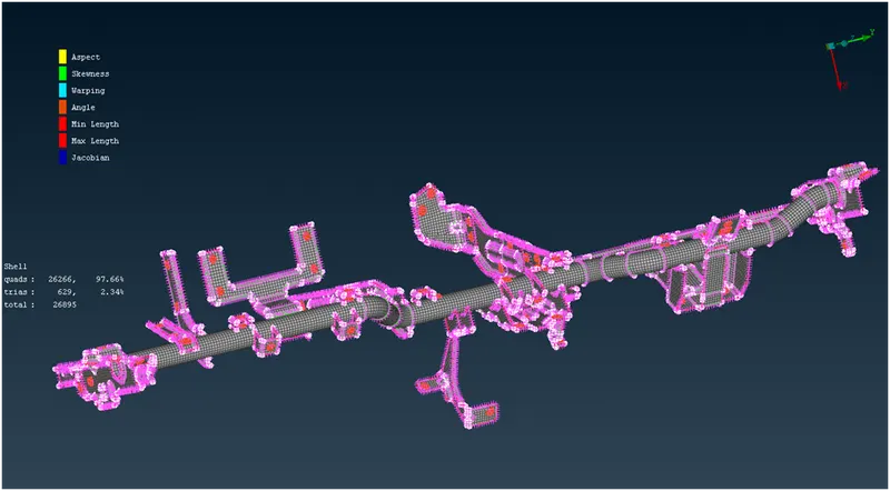
(Image-16: Desired result)