Week - 4 - 2D meshing for Plastic components
Optimized 2D Meshing for Plastic Component
Problem Description:
In this exercise, the Meshing operation for the component ‘Plastic bottle cap Model’ is going to perform after Geometric cleanup, defeaturing, topo operations. The main aim of this challenge is to create Mid surface along with appropriate mesh within the quality criteria. Also thickness has to be assigned in the model.
Introduction:
This Exercise consist only one Component, and this component has variable thickness at different features. In order to arrive appropriate mesh features are segregated and new PIDs assigned based on the thickness category. The component name is Symmetry Bottle Cap.
|
S.NO |
PID Name |
Feature Thickness |
Average PID Thickness assigned |
|
1 |
Button |
2.3 to 2.25 mm thk |
2.275 mm |
|
2 |
Ribs |
0.25 to 1 mm thk |
0.625 mm |
|
3 |
Fins |
0.5 to 0.8 mm thk |
0.65 mm |
|
4 |
Other Body Parts |
1 to 1.5 mm thk |
1.25 mm |
<!-- [if !supportLists]-->· <!--[endif]-->In this exercise, there are many features and these features are in different thickness. Hence different mid surface are going to extracted and then meshing operation are going to perform. It has been noted that most of the features in this component has been modeled symmetrically along with YZ PLANE.
<!-- [if !supportLists]-->· <!--[endif]-->Few features like fins and buttons are not modeled symmetrically but these features can be circular patterned based on the center axis of the component.
<!-- [if !supportLists]-->· <!--[endif]-->It has been noted that there are 12 fins and 26 buttons in this component.
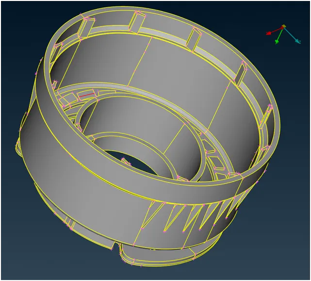
(Image-1: Symmetric Model of Plastic bottle cap)
The following steps has been done for the mesh extraction
<!-- [if !supportLists]-->· <!--[endif]-->Geometry clean up
<!-- [if !supportLists]-->· <!--[endif]-->Mid Surface Extraction
<!-- [if !supportLists]-->· <!--[endif]-->Mesh creation within specified quality criteria.
<!-- [if !supportLists]-->1) <!--[endif]-->Geometry Cleanup:
Initially the model file (step format) has been opened in the ANSA. Because of file translation or importing from neutral format
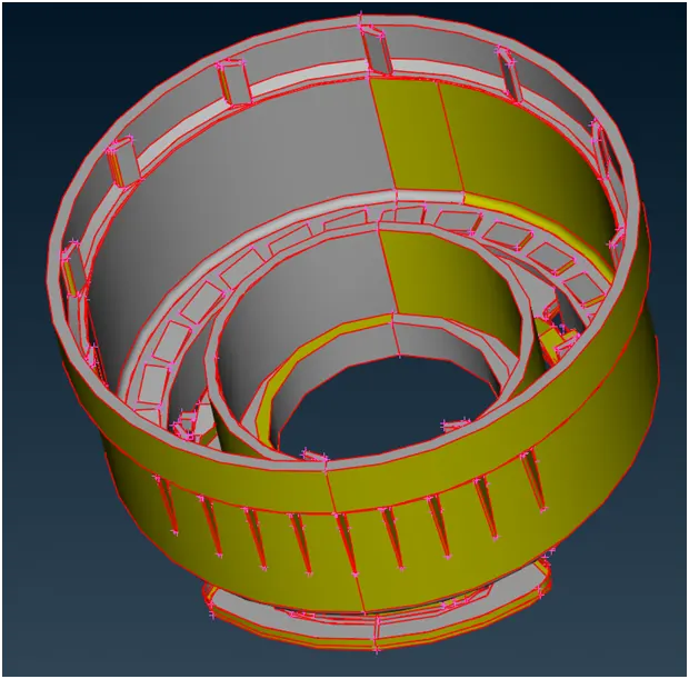
(Image-2: Geometry Check without topo)
Step-1: Topo operation performance to create associated edges
Step-2: Orientation checks have to be done. Inner faces yellow color and outer face Grey color assigned.
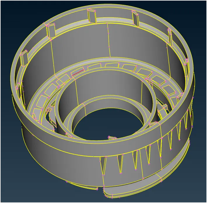
(Image-3: Orientation check)
Step-3: Geometry Checks (Tools -> Checks -> Geometry)
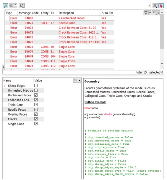
(Image-4: Geometry error)
Step-4: Fixing Geometric error (by automatic or manual error fixing). Here both Error fixing methods used based on surface twist.
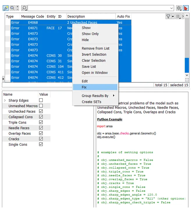
(Image-5: Geometry automatic error Fixing)
If required new curves has been created and then new surface has been generated with the help of surface cons option
Step-5: Cons resolution adjustments, perimeter -> length -> specify length 1 mm (average element size).
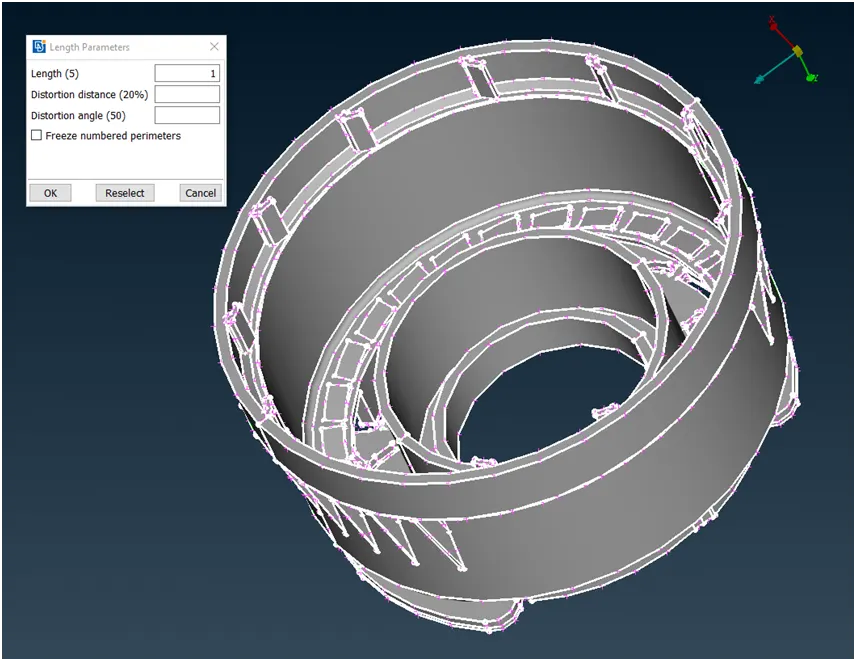
(Image-6: Cons Resolution adjustment)
Step-6: Defaturing smaller features whose size less than minimum element size (Feature sizes less than 0.5 mm). In this section few fillet radius are neglected while extracting Mid surfaces because its feature sizes are very less.
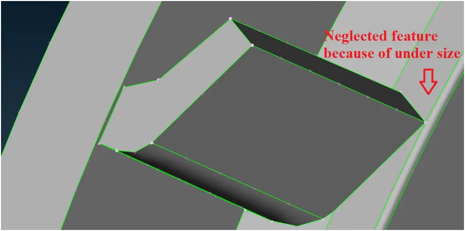
(Image-7: Defeaturing)
2) Mid Surface Extraction:
After geometric clean operation Mid-Surface has to be extracted with the help of auto mid surface or using offset option.
<!-- [if !supportLists]-->· <!--[endif]-->If auto mid surface is used, we have to assign appropriate color coding to appropriate face.
Red or green Color: Inner or outer Surface
Blue Color: Thickness side.
But because of many uneven features, Manual mid surface extraction preferred.
<!-- [if !supportLists]-->· <!--[endif]-->Here manual Mid-surfaces extracted by using Middle menu and offset Menu because of uneven feature thickness distribution
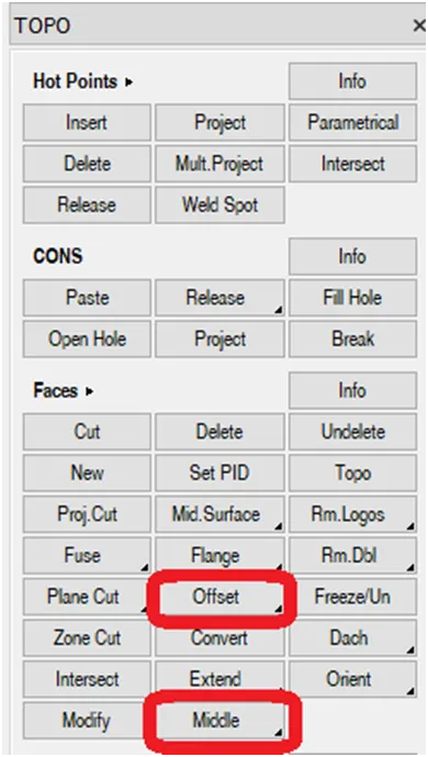
(Image-8: Typical options used for Mid surface Extraction)
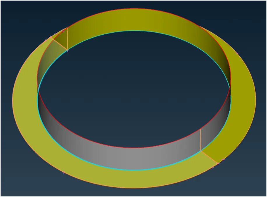
(Image-9: Typical Mid surface Extracted using Middle option)
<!-- [if !supportLists]-->· <!--[endif]-->In order to reduce computational time, only one typical feature’s mid surfaces are extracted amongst identical features. At later stage it will be transformed along with entities.
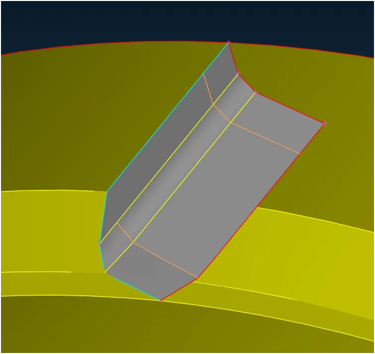
(Image-10: Typical fin Mid surface Extraction)
<!-- [if !supportLists]-->· <!--[endif]-->Similarly, all identical features are segregated and then typical feature surface extracted. Based on this there are 4 property IDs created along with parent component.
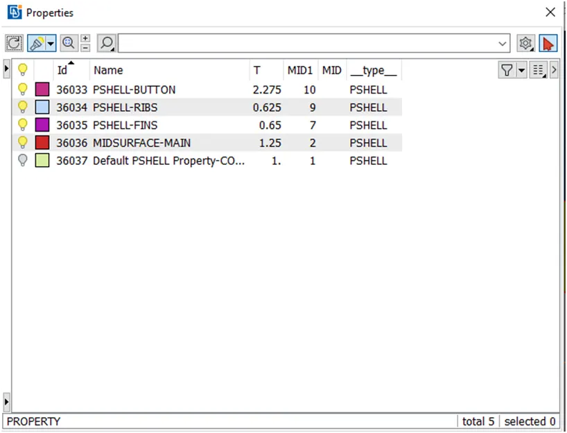
(Image-11: Property manager)
<!-- [if !supportLists]-->· <!--[endif]-->Another computational time saving done by, extracting only half model Mid surface which are symmetric with respect to YZ plane by neglecting few features like fins and button because it is not symmetric to the working plane.
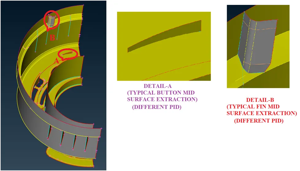
(Image-12: Half Model)
<!-- [if !supportLists]-->· <!--[endif]-->Nodes adjustment by sliding option and Nodes marking has been done.
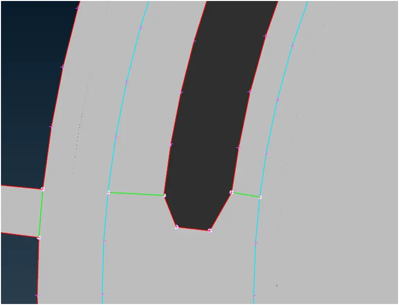
(Image-13: Nodes adjustment and Nodes marking)
Finally the Meshing operations are going to carry after performing these steps.
3) Mesh creation within specified quality criteria:
The quality criteria and mesh parameter for this exercise are shown below,
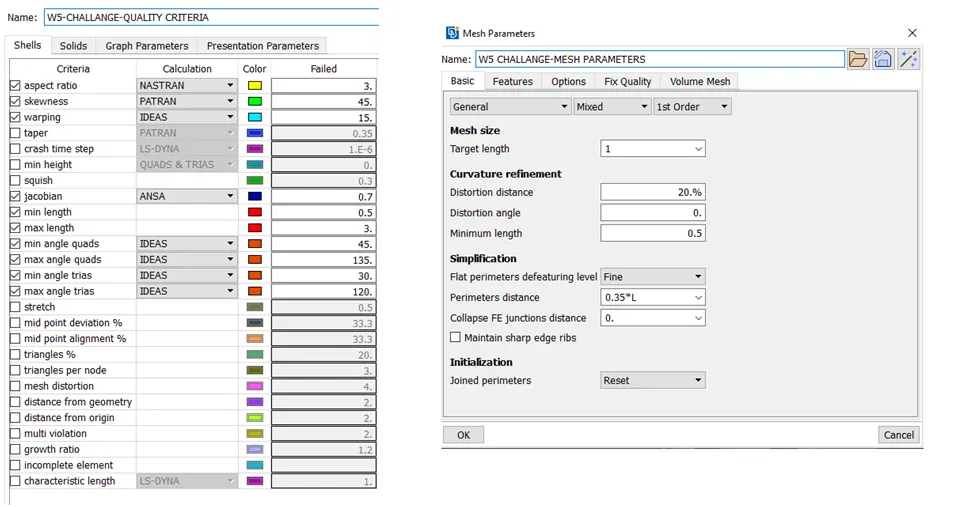
(Image-14: Quality criteria)
<!-- [if !supportLists]-->· <!--[endif]-->Using Cut/ Join/ proj cut Menu under Macros cons has been removed or added based on requirement. Also unwanted hot points have been removed by using Delete menu under hot points.
<!-- [if !supportLists]-->· <!--[endif]-->Free option under Mesh generation used to generate free mesh.
<!-- [if !supportLists]-->· <!--[endif]-->Elements have been splitted and joined at some areas to reduce trias. Collapse option used to minimize trias.
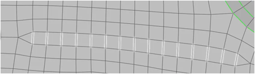
(Image-15: Tias reduction using collapse option)
<!-- [if !supportLists]-->· <!--[endif]-->If mesh flow is not reaches the quality criteria, then Reconstruct and Improve option under shell Mesh will be used to avoid low quality mesh
<!-- [if !supportLists]-->· <!--[endif]-->Move command used in certain area to avoid element failure where hot points are very close to each other
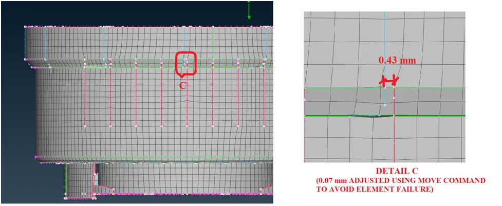
(Image-16: Typical Meshing at feature areas)
<!-- [if !supportLists]-->· <!--[endif]-->After creating half component mesh the other half has been mirrored with respect to YZ plane
<!-- [if !supportLists]-->· <!--[endif]-->If required Topo operation done at symmetric edges. Then Joined unwanted cons using Join command under Macros.
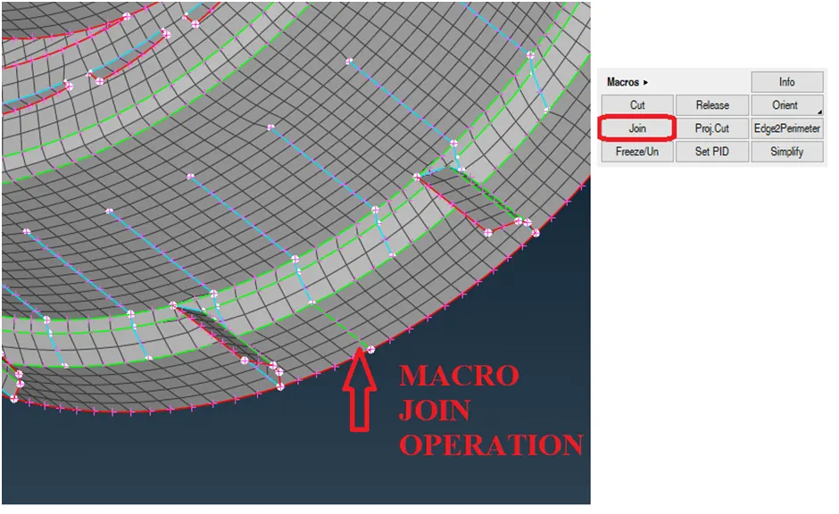
(Image-17: Typical Macro operation)
<!-- [if !supportLists]-->· <!--[endif]-->Then circular pattern has been created for fins (12 nos) and Buttons (26 nos) based on the symmetric axis using Transform àrotate under utility menu option
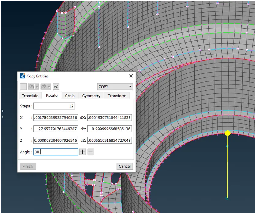
(Image-18: Typical Transform operations of Features)
<!-- [if !supportLists]-->· <!--[endif]-->Ensured all features should topologically connect with its associated faces by using Topo operation.
<!-- [if !supportLists]-->· <!--[endif]-->After topo operation there may be mesh loss in few features. Remesh has been performed at required faces.
<!-- [if !supportLists]-->· <!--[endif]-->Finally thickness has been assigned.
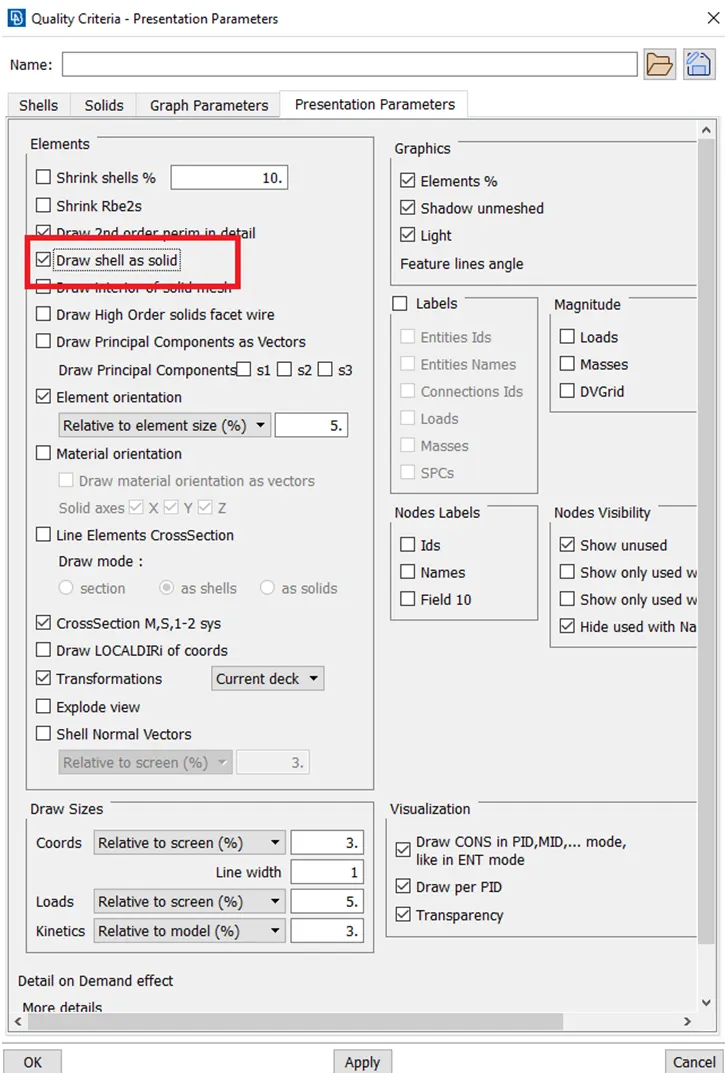
(Image-19: Thickness assignment)
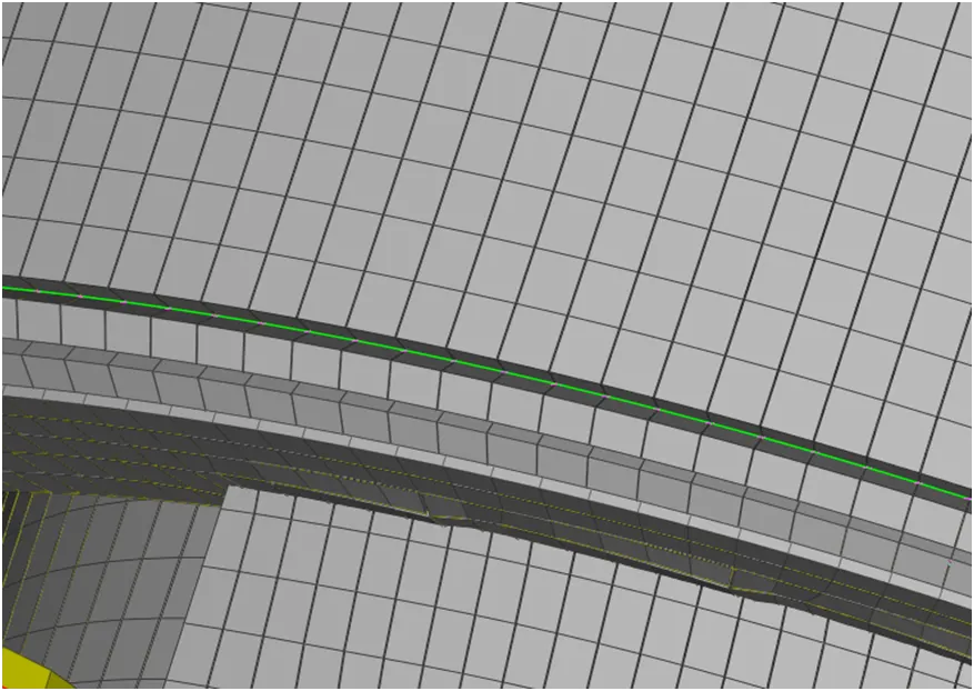
(Image-20: Thickness assignment)
Result:
After performing all operations, the mesh with minimum triangular element along with no off elements has been obtained successfully. Total Trias percentage obtained in this exercise is 1.23 % without any off elements and also thickness assigned.
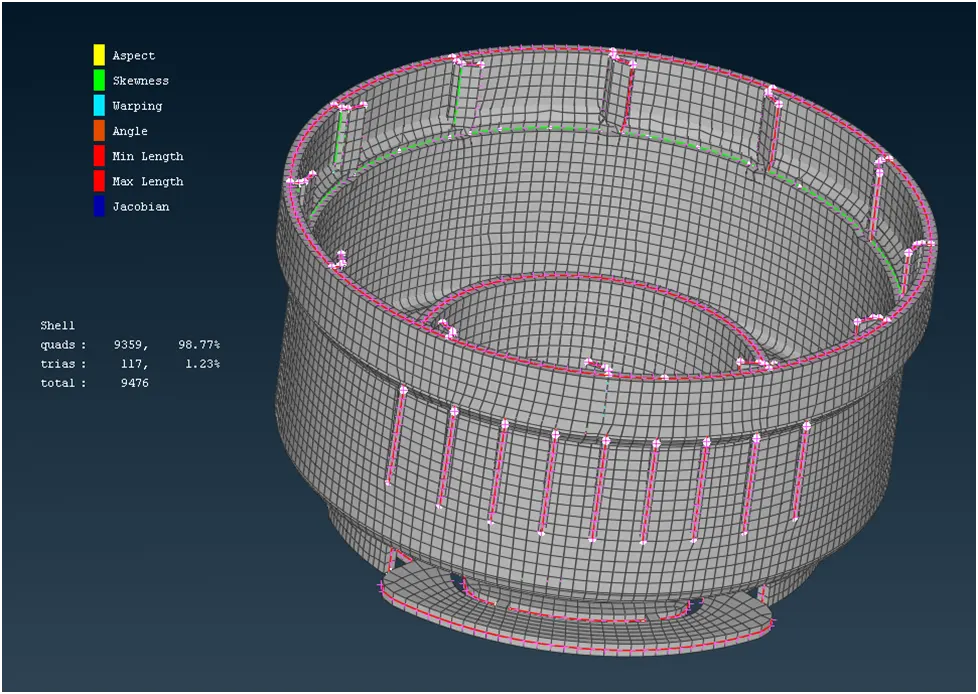
(Image-21: Desired result)