Week 3 - 2D meshing for Sheet metal
Optimized 2D Meshing in Hood model, a sheet Metal Component
Problem Description:
In this exercise, a hood model, a sheet metal component having 5 sub parts are going to perform the Meshing operation after completing Geometric cleanup, defeaturing, topo operations. The main aim of this exercise is to learn how to created 2D mesh within the specified quality criteria.
Introduction:
This sheet metal hood model consists of 5 sub parts and it has been designed symmetrically with respect to X-Z plane. In this model there are much geometrical error like silver edges, spikes, needle faces and some other geometric disturbances. Also many smaller features are there. Preliminarily we have to perform geometric cleanup, so only we can achieve appropriate mesh within specified quality criteria. There are 3 major steps in this challenge.
- Geometry clean up
- Mid Surface Extraction
- Mesh creation within specified quality criteria.
1) Geometry Cleanup:
In this section geometrical disturbance like silver edges, spikes, needle faces have been going to remove with the help of geometric checks. Smaller features like radius less than 2 mm has to be removed because it will reduce quality of mesh. Geometric clean ups steps are as follows,
- Geometric check
- Defeaturing
- Increasing Cons Resolutions
1.1) Geometric Check:
This option avails under Tools -> Checks -> Geometry. After performing the execute button geometrical errors or any disturbance which has less silver tolerance will be displayed. Error like overlaps, cracks, needle faces etc will be displayed
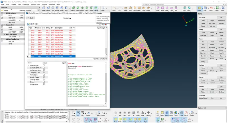
(Image-1: Geometry Check)
These errors are removed by followings steps,
Step-1: Releasing Cons at problematic area
Step-2: Deleting hot points at problematic area
Step-3: Deleting unwanted Needle edges or cons
Step-4: Adding additional hot points if necessary
Step-5: Performing topo operation
Step-6: Adding/ deleting Surface if necessary
After performing these steps the Geometrical error will be rectified then we have to perform Defeaturing operation.
1.2) Defeaturing:
Defeaturing is nothing but removing the smaller feature line fillet radius or any other features having sizes less than specified minimum element size. In this exercise 2mm is specified as minimum element size. So These feature are removed in this section with the help of surface delete, adding or removing face cuts etc.
1.3) Increasing Cons Resolutions:
In this section feature’s (like fillet, holes etc) resolution has been improved to maintain same perimeter length in order to achieve the even mesh. Steps are as follows,
Step-1: Under classic mesh option click perimeter -> length -> specify length 5mm (average element size). Entire surface cons resolution will be adjusted accordingly.
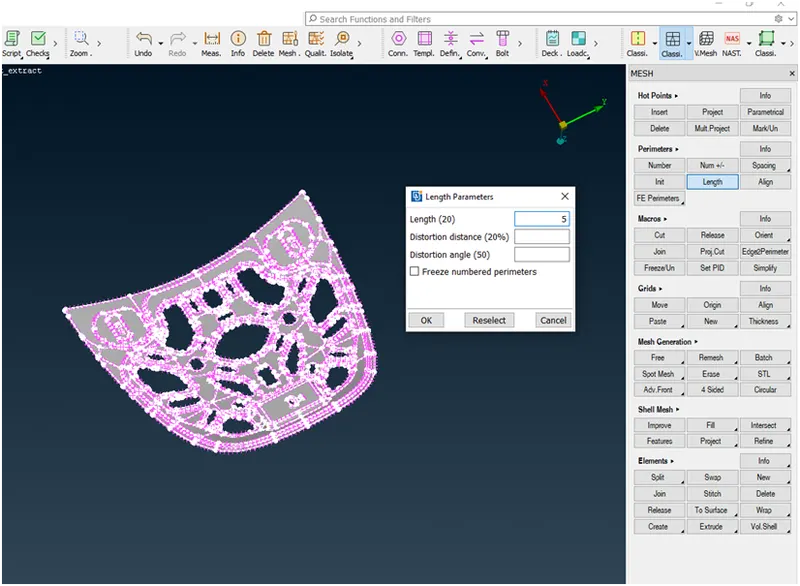
(Image-2: Cons Resolution adjustment)
Step-2: Then face orientation has been adjusted. Grey color to top face and yellow to bottom face.
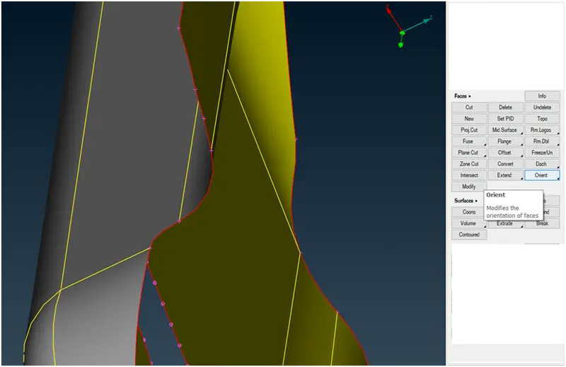
(Image-3: Orientation check)
2) Mid Surface Extraction:
After geometric clean operation Mid-Surface has to be extracted with the help of auto mid surface or using offset option.
- If auto mid surface is used, we have to assign appropriate color coding to appropriate face.
Red or green Color: Inner or outer Surface
Blue Color: Thickness side
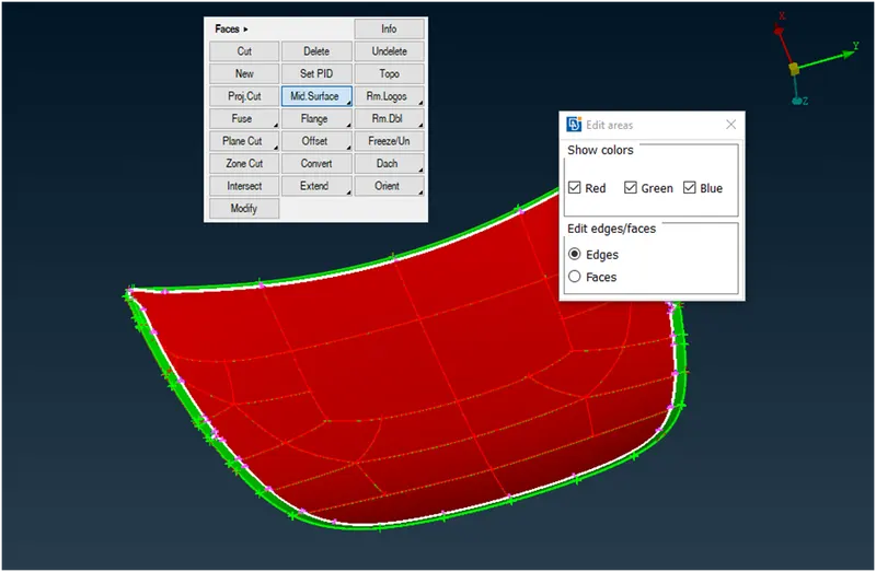
(Image-4: Mid surface Extraction)
- If offset surface is used, we have to pick either all inner surface or outer surface and have to offset face to 0.5 times of thickness in-order to achieve mid-surface. Since this part is 0.75mm this so offset value has been given is 0.375mm to extract mid surface.
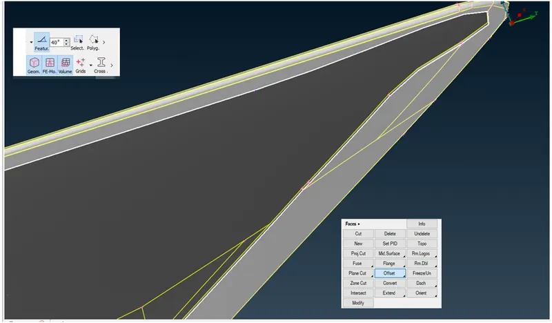
(Image-5: Mid surface Extraction via offset)
- After Mid-surface extraction, make sure all features like holes, slots etc should have even number of nodes with the help of number menu under
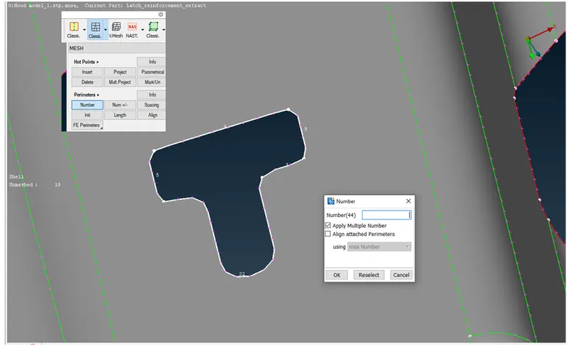
(Image-6: Nodes adjustment)
- Then holes should be aligned parallel to one edge with the help of slide menu under perimeter in order to get smooth mesh flow.
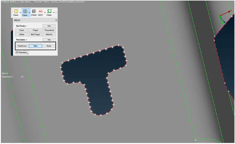
(Image-7: Nodes alignment)
- Since these aligned holes are subjected to change its orientation and its number while doing meshing operations. So this nodes are fixed with the help of mark/un option under hot points.
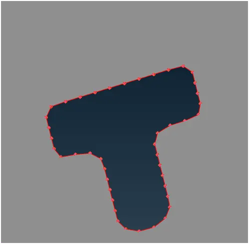
(Image-8: Nodes marking)
Finally the Meshing operations are going to carry after performing these steps.
3) Mesh creation within specified quality criteria:
There are two different shape function available in 2d meshing
- Tria/Tet elements
- Quad/brick elements.
Triangular element also called as Constant strain triangle (CST). Triangular element uses use linear shape functions. The value of stress and strain concentration will be constant in whole elements. The approximation may create lot of error in real situations
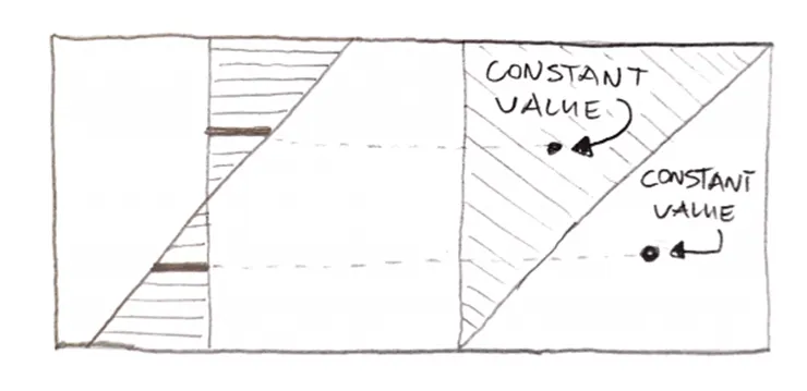
(Image-9: Constant Stain Triangle)
In the case of quad elements, it uses use bilinear/ trilinear shape functions. It is less stiffer than triangular element and offers additional mode of deformation. So quad elements has been proffered over the triangular element in this 2D meshing
3.1) Meshing:
In this exercise Quad mesh has been preferred to perform 2D meshing operation. Quality Criteria are shown below
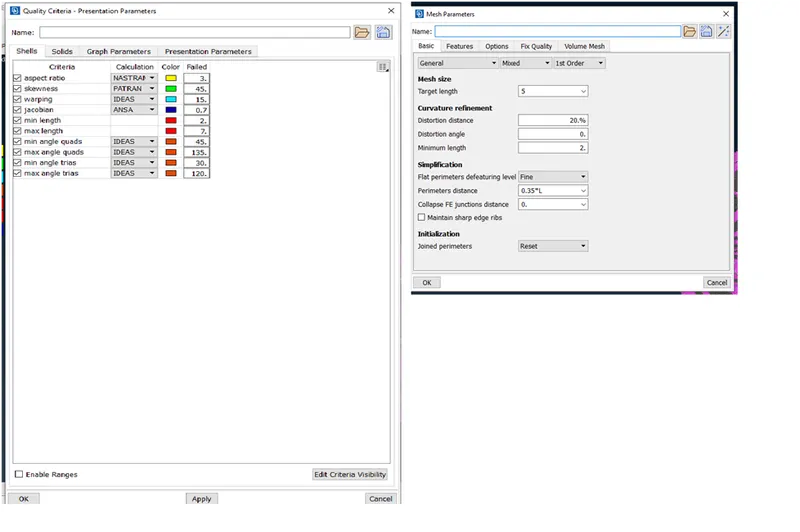
(Image-10: Quality criteria)
Step-1: Using Cut/ Join/ proj cut Menu under Macros cons has been removed or added based on requirement.
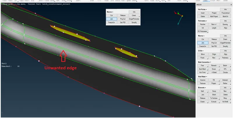
(Image-11: Unwanted Edge removal)
Step-2: Unnecessary hot points are deleted using Delete menu under hot points.
Step-3: Free option under Mesh generation used to generate free mesh.
Step-4: In fillet area, even though the feature has average element perimeter, it has been split into two elements.
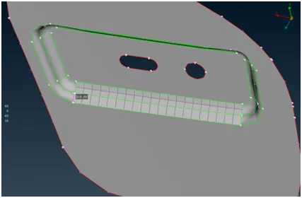
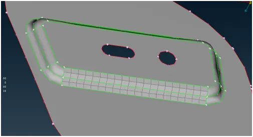
(Image-12: with more chordal deviation) (Image-13: with Less chordal deviation)
Chordal deviation is to determine how good the elements captured at curves. When fillet size is smaller than the element size, this error occurs.
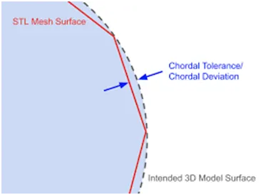
Image-14: chordal deviation
Step-5: If mesh flow is not reaches the quality criteria, then Reconstruct option under shell Mesh will be used to avoid low quality mesh
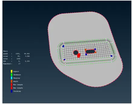
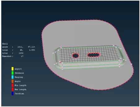
(Image-15: Mesh before reconstruct) (Image-16: Mesh after reconstruct)
Step-6: If requires Num +/- under perimeter used to increase number of nodes at required edges.
Step-7: Split/swap/join options under Elements menu are used to split element or swap the tria or to join two elements.
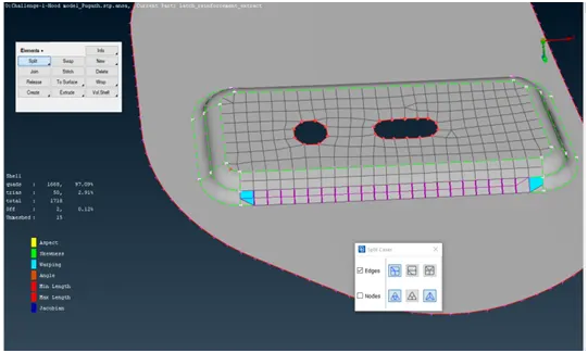
(Image-17: Splitting elements)
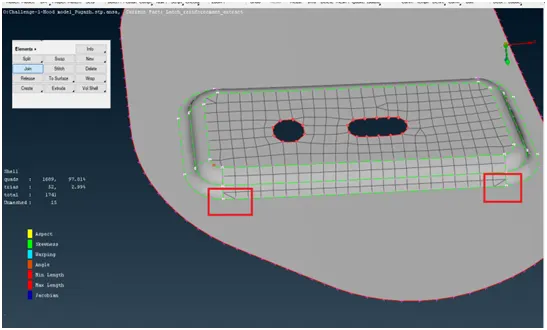
(Image-18: Joining elements)
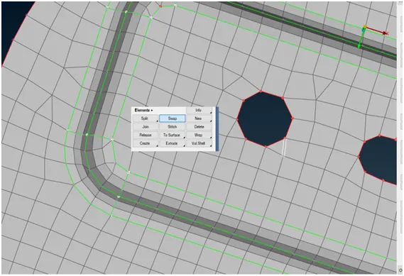
(Image-19: Swapping elements)
Result:
After performing all operations in all components, the mesh with minimum triangular element has been obtained. Total Trias percentage (5 components) obtained in this exercise is 1.54% without any off elements.