Project 1 - Meshing of Floor Panel
Optimized 2D Meshing of Floor panel with thickness assignment
Problem Description:
In this exercise, the Meshing operation for the component Floor panel is going to perform after Geometric cleanup, defeaturing, topo operations. The main aim of this Project-1 is to create Mid surface along with appropriate mesh within the quality criteria. Also thickness has to be assigned in the model.
Introduction:
This sheet metal Exercise consist only one Component, with average thickness 1 mm. The component name is Floor panel.
|
S.NO |
Average Component Thickness |
Distance to offset for Mid-surface Extraction |
|
1 |
1 mm thk |
0.5 |
- In this exercise there is an additional sheet component has been seemed observed and probably it was welded to the base component and together called as floor panel.
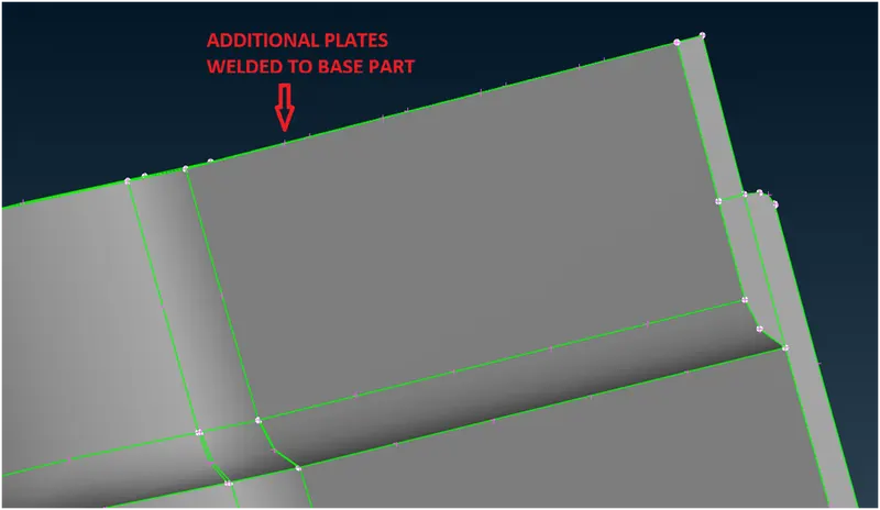
(Image-1: Two different parts)
- So two mid surface are going to be created and then meshing operation are going to perform
The following steps has been done for the mesh extraction
- Geometry clean up
- Mid Surface Extraction
- Mesh creation within specified quality criteria.
1) Geometry Cleanup:
Initially the model file (step format) has been opened in the ANSA. Because of file translation or importing from neutral format, there will be some data loss (like losing cons associativity).
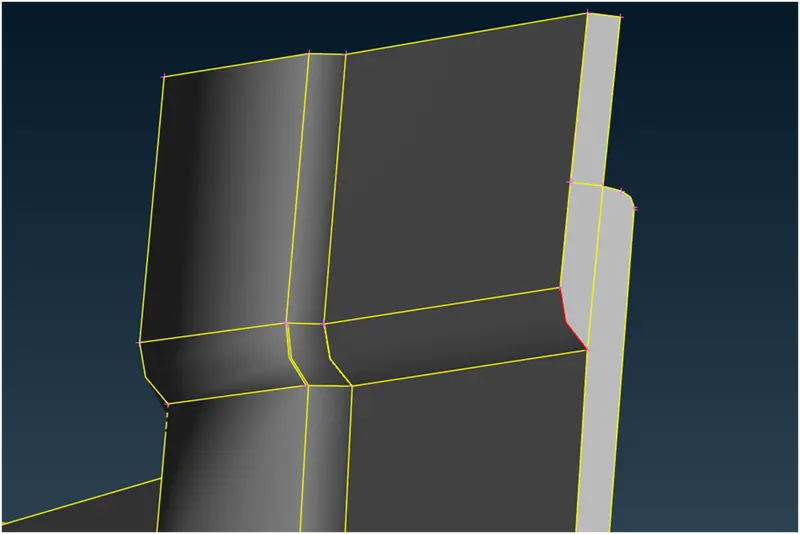
(Image-2: Geometry Check without topo)
Step-1: Topo operation performance to create associated edges
Step-2: Orientation checks
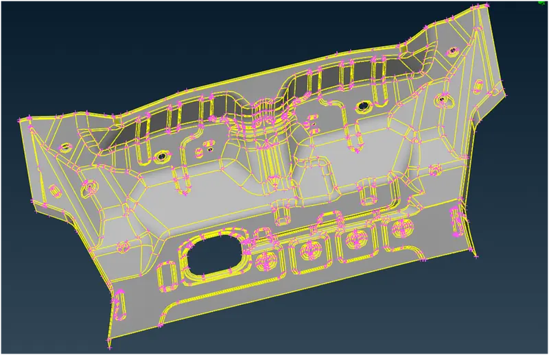
(Image-3: Orientation check)
Step-3: Geometry Checks (Tools -> Checks -> Geometry)
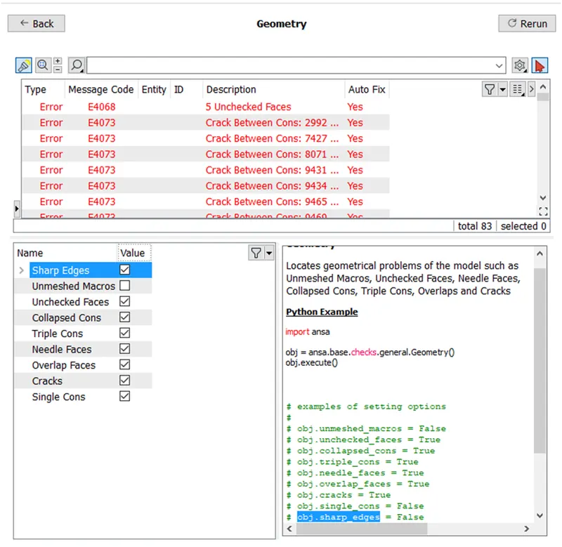
(Image-4: Geometry error)
Step-4: Fixing Geometric error (by automatic or manual error fixing). Here both Error fixing methods used based on surface twist.
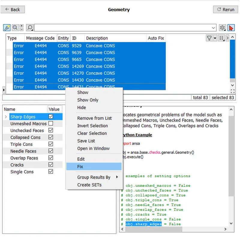
(Image-5: Geometry automatic error Fixing)
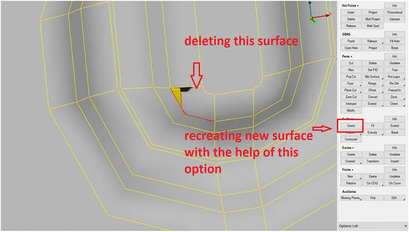
(Image-6: Geometry manual error Fixing)
If required new curves has been created and then new surface has been generated with the help of surface cons option
Step-5: Cons resolution adjustments, perimeter -> length -> specify length 5 mm (average element size).
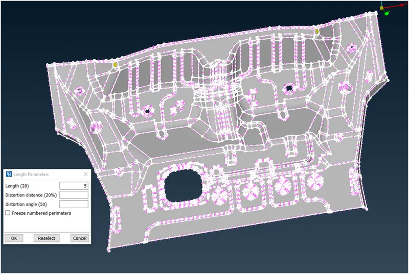
(Image-7: Cons Resolution adjustment)
Step-6: Defaturing smaller features whose size less than minimum element size (Feature sizes less than 2 mm)
2) Mid Surface Extraction:
After geometric clean operation Mid-Surface has to be extracted with the help of auto mid surface or using offset option.
- If auto mid surface is used, we have to assign appropriate color coding to appropriate face.
Red or green Color: Inner or outer Surface
Blue Color: Thickness side.
Here manual offset method used to create mid surface because of uneven thickness distribution 1 to 1.2 mm
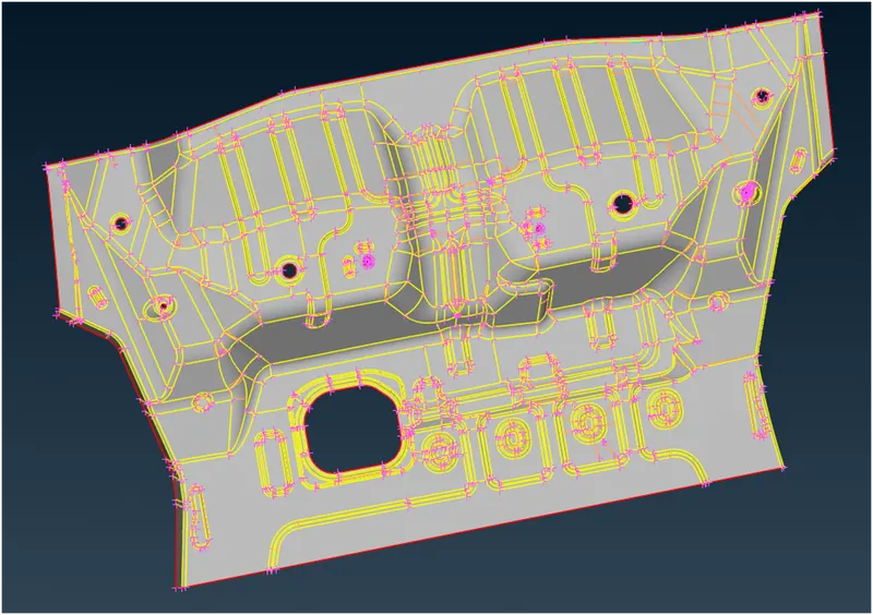
(Image-8: Mid surface Extraction of property ID-1 via off set option)
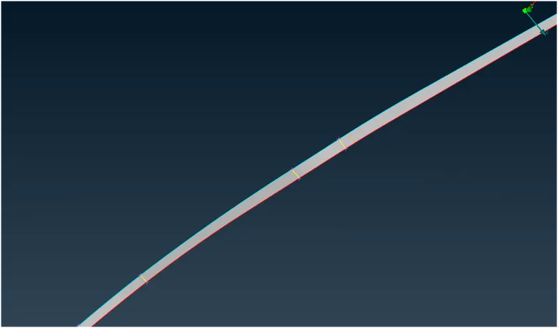
(Image-9: Mid surface Extraction of property ID-2 via off set option)
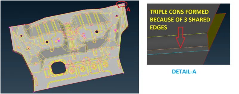
(Image-10: Mid surface Extraction all component via off set option)
Hence two properties ID (MID SURFACE) has been created along with the default component.
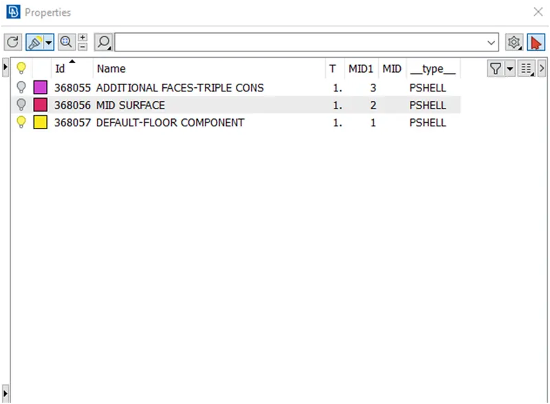
(Image-11: Property manager)
- No faces are identical. So Symmetric face split is not feasible
- Nodes adjustment by sliding option and Nodes marking has been done.
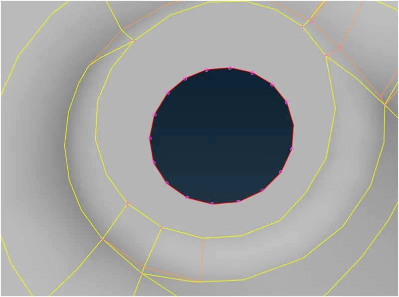
(Image-12: Nodes adjustment and Nodes marking)
Finally the Meshing operations are going to carry after performing these steps.
3) Mesh creation within specified quality criteria:
The quality criteria and mesh parameter for this exercise are shown below (FOR PROJECT-1),
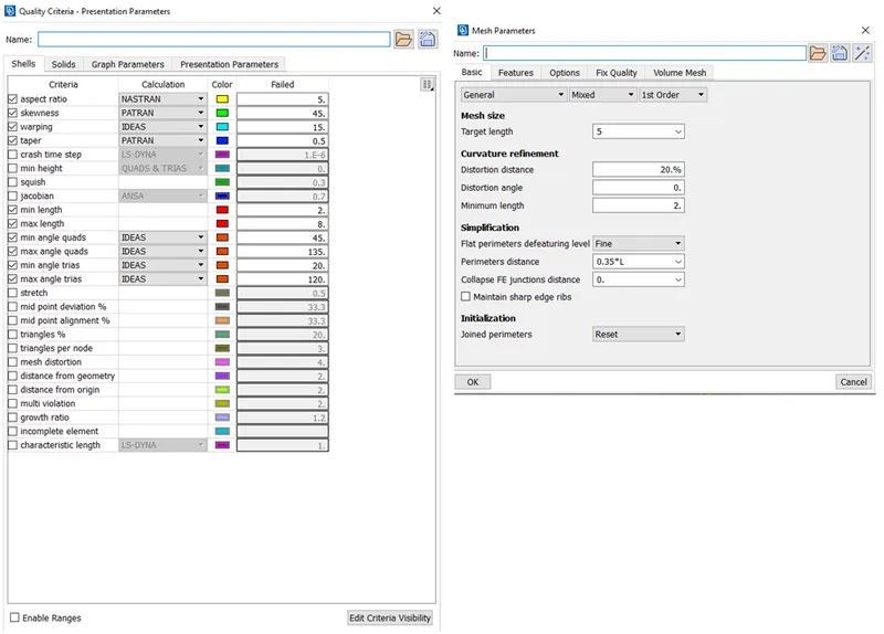
(Image-13: Quality criteria)
- Using Cut/ Join/ proj cut Menu under Macros cons has been removed or added based on requirement. Also unwanted hot points have been removed by using Delete menu under hot points.
- Free option under Mesh generation used to generate free mesh.
- Elements have been splitted and joined at some areas to reduce trias. Collapse option used to minimize trias
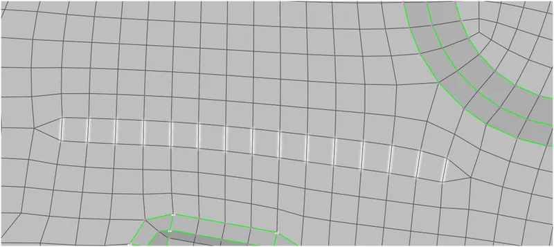
(Image-14: Tias reduction using collapse option)
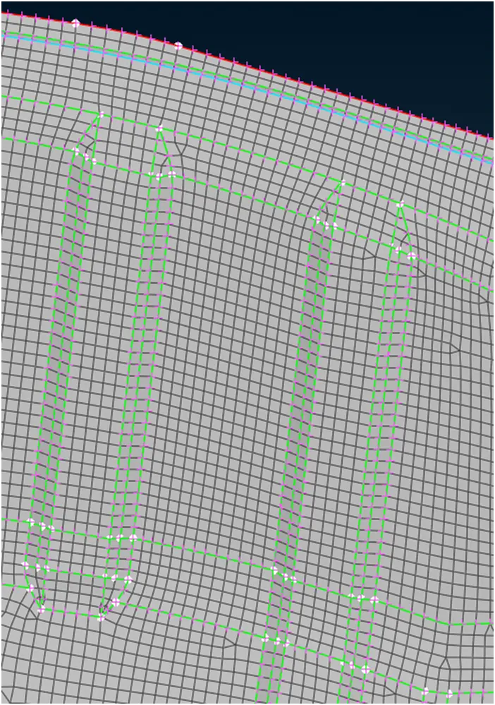
(Image-15: Typical Meshing at feature areas)
- If mesh flow is not reaches the quality criteria, then Reconstruct and Improve option under shell Mesh will be used to avoid low quality mesh
- Finally thickness assigned
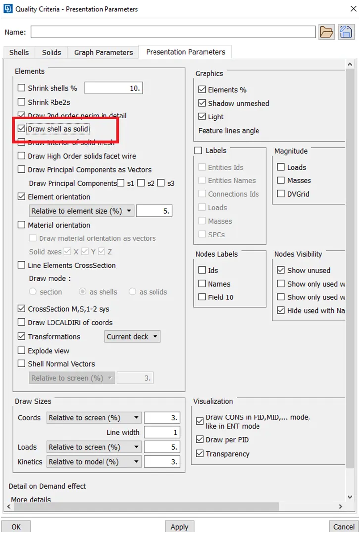
(Image-16: Thickness assignment)
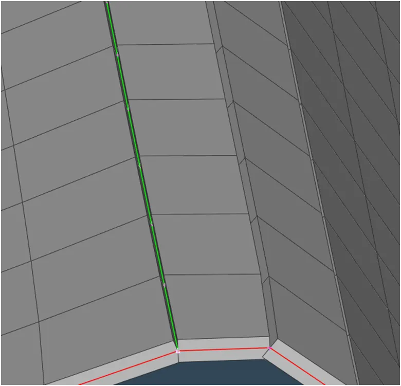
(Image-17: Thickness assignment)
Result:
After performing all operations in all components, the mesh with minimum triangular element has been obtained. Total Trias percentage obtained in this exercise is 2.96 % without any off elements and also thickness assigned.
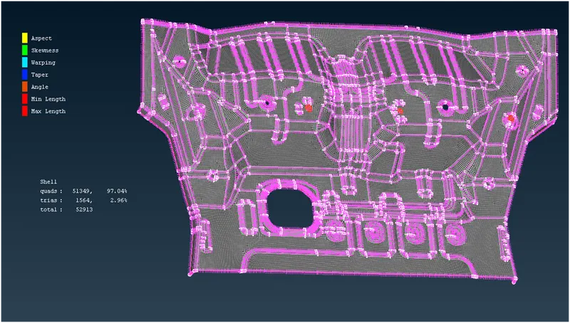
(Image-18: Desired result)