Week 4 - 2D Meshing for Sheet Metal
OBJECTIVE
For the given CCB CAD model clear geometrical errors and generate mesh with the above given quality criteria.
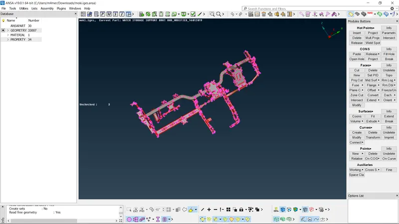
INITIAL CAD IMAGE
PROCEDURE
1.Geometry clean up
Check for geometrical errors using Geometry check manager.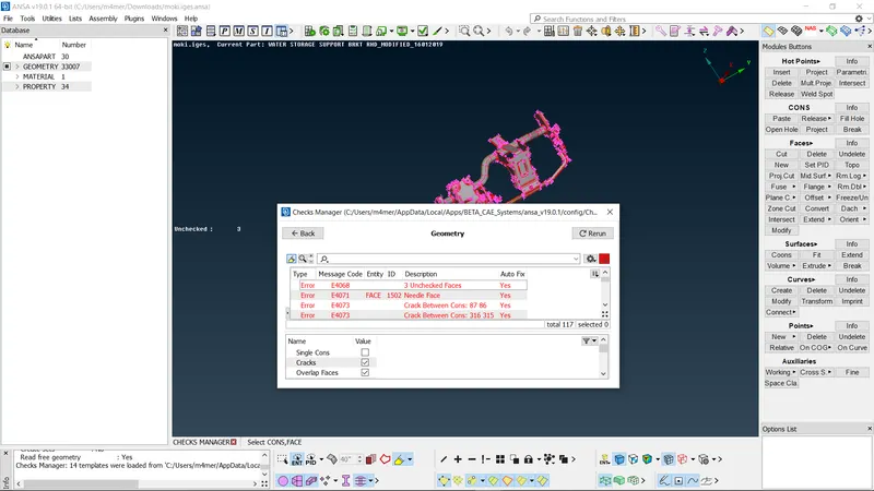
2.Mid surface generation.
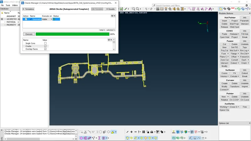
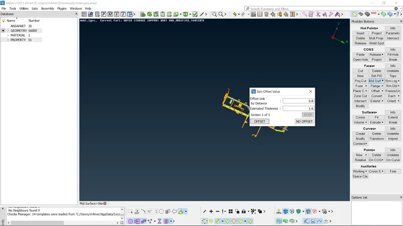
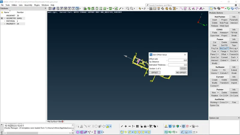
Generated mid surface for the cad model using MID SURFACE tool in FACES.As this model have parts with different thickness we have to given different offset values according to the respective part thickness.
*Select FACES>> MID SURFACE
*Box select whole cadd model.
*By clicking middle mouse button we can create mid surface for different parts with different offset values.
3.MESH GENERATION
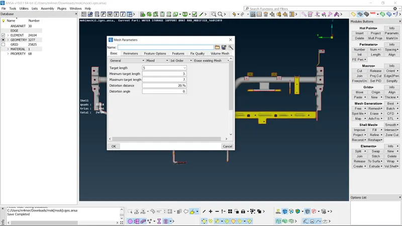
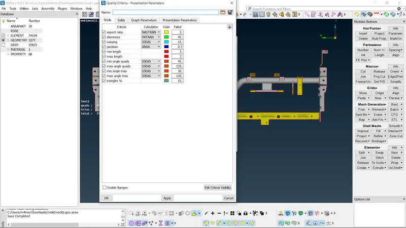
*We have to give required mesh parameters and quality criteria from UTILITY
*Generate mesh using MESH GENERATION>>BEST
*As in this model have different thickness for different parts we have to give offset values accroding to respective part's thickness.
* So after selecting whole model pressing midlle mouse button will take us to each part were we can assign offset value according to that part's thickness.
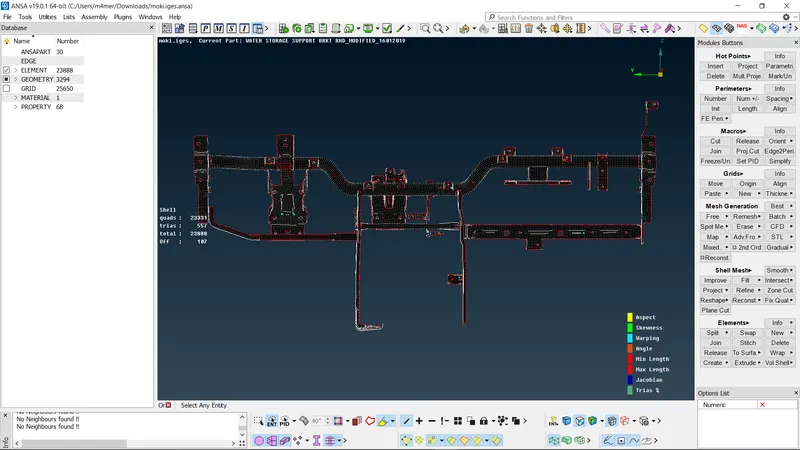
*After succesfully generationg mesh we can clear off elements using tools like RECONSTRUCTION,SMOOTH,SPLIT,JOIN etc.
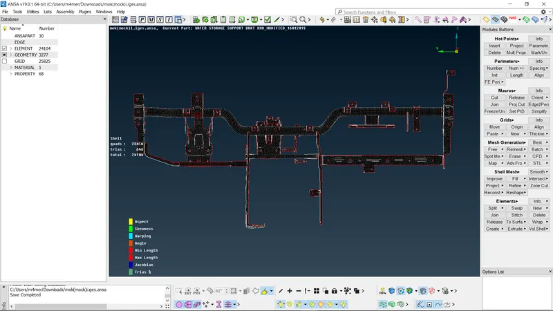
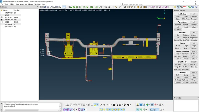
FINAL MODEL