Week - 4 - 2D meshing for Plastic components
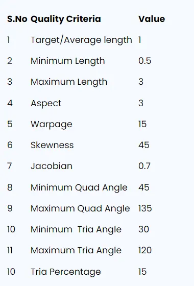
AIM :- Mesh the plastic bottle cap model with the specified element quality criteria to ensure optimal performance and durability.
Objective :-
-
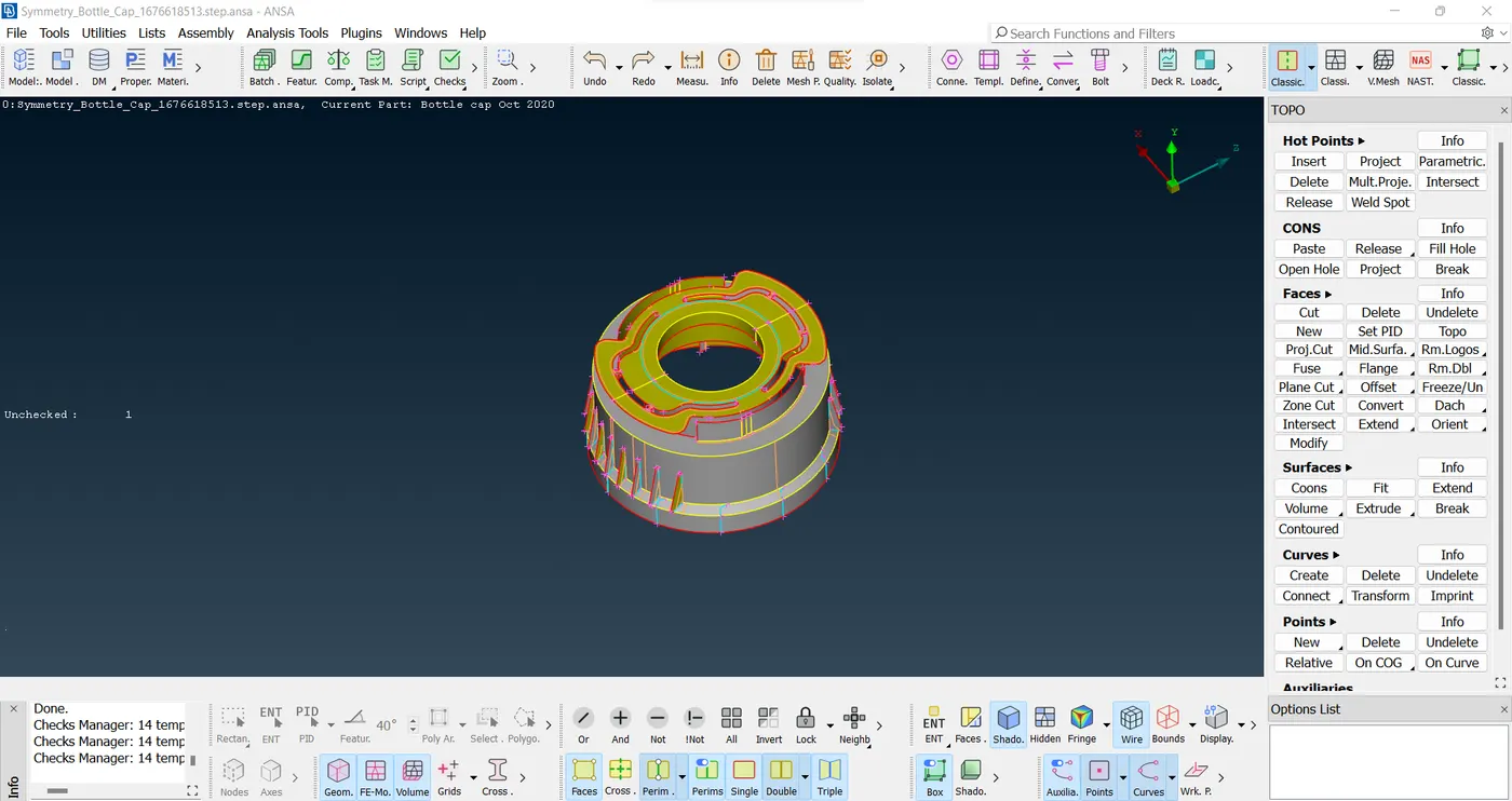
Ensure the detection and rectification of geometrical errors by employing appropriate mid-surfacing techniques on the provided model. This will allow for the creation of accurate mid surfaces.
-
Establish the PID (Proportional-Integral-Derivative) and thickness settings for all mid surfaces that have been generated. This step is crucial to maintain uniformity and consistency throughout the model.
-
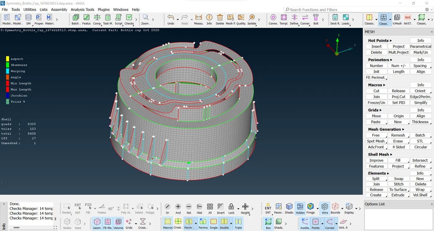
Perform the meshing process on the designated component, adhering to the defined element quality criteria. This will result in a well-structured and optimized mesh for further analysis and simulations.
- PROCEDURE :-
- IMPORTING AND MODEL GEOMETRY CHECK:
-
Begin by importing the provided Hood Model into ANSA by navigating to File > Open.
-
Once the CAD Model has been successfully imported, proceed to perform a comprehensive geometry check by going to Tool > Checks > Geometry in ANSA.
-
Upon executing the geometry check, any errors related to the model will be displayed. Utilize the automatic fix option to address and resolve as many issues as possible. For those errors that cannot be automatically cleared, use various options available in Topo to manually rectify them. This will ensure a clean and accurate model geometry for subsequent analysis and simulations.
- MID-SURFACE CREATION:
- Mid-surfacing is a critical step in the process, and various methods can be employed to achieve it. The automatic method is often preferred for its efficiency. In this approach, the mid surfaces are created using the faces>offset option, and the PID is manually set to meet specific requirements. An alternative automatic option is faces>middle, where the PID is automatically determined based on the model's characteristics. Additionally, in certain cases, the middle curve is utilized strategically to create faces by effectively joining the curves where necessary.
- MESHING:
-
Once the mid surface has been successfully generated, we can proceed to the meshing phase.
-
Begin by configuring the desired Quality Criteria. Navigate to Utilities > Quality Criteria Option and input the specified Quality Criteria Values.
-
Next, access Utilities > Mesh Parameters to set the Average Value, Minimum, and Maximum Value for 2D Meshing.
-
Select the desired component for meshing and define the Perimeter Length and Macro Length values in Mesh > Perimeters > Length Option.
-
Optimize the mesh by choosing Mesh > Mesh Generation > Best Mesh.
-
For further refinement, utilize Shell Mesh > Reconstruct to reorganize the mesh and apply Shell Mesh > Smooth Option to improve the mesh flow.
-
Enhance the mesh quality by reducing or eliminating trias through Elements > Split / Swap / Joint option and Grids > Paste Option.
-
Finally, improve the visualization by accessing Quality Parameter > Presentation Parameters. Choose the "Draw shell as solid" option, apply the settings, and click Ok to finalize the meshing process.
- LEARNING OUTCOMES :-
-
Gained proficiency in identifying and rectifying geometry errors in models, ensuring model accuracy and reliability.
-
Acquired skills in mid-surfacing complex components with varying thickness, facilitating efficient analysis and simulations.
-
Developed expertise in performing 2D meshing for intricate molded components, enabling precise and effective mesh generation for further analysis.