Project 1 - Meshing of Floor Panel
Objective: - The objective of this project is to perform 2D meshing on a floor panel made of sheet metal while adhering to specified element quality criteria. This will be carried out after completing the geometry clean-up and mid-surfacing steps.
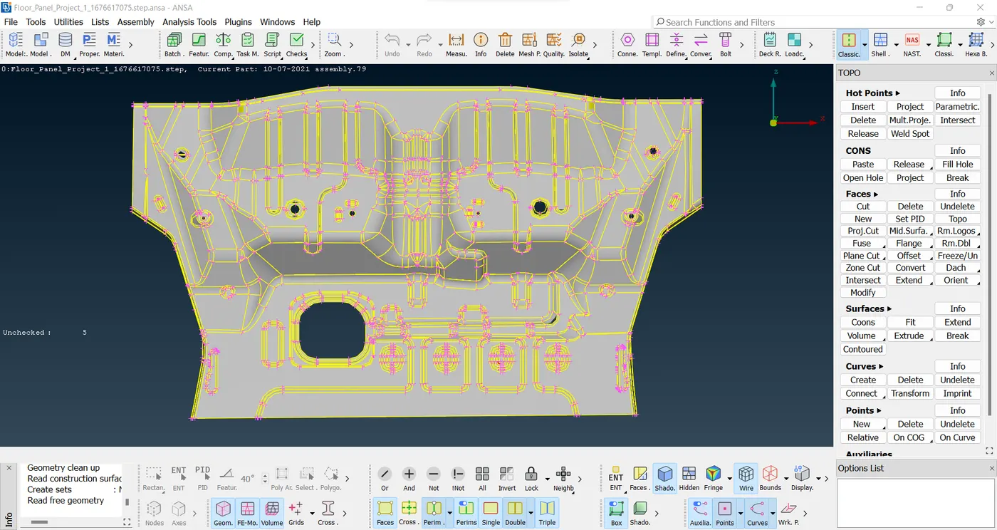
- CAD Model Image :-
- PROCEDURE :-
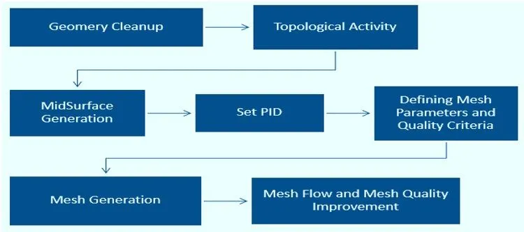
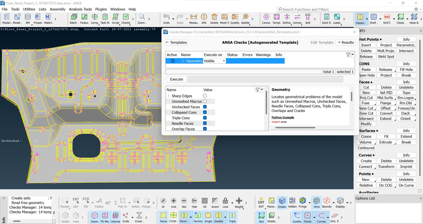
- Geometry Clean-up: - When importing a model from other software to ANSA, geometrical deviations may arise, requiring resolution before advancing to subsequent steps. To address these issues, utilize the Geometry Check Tools in ANSA, which may identify needle faces and unchecked faces errors common during imports. Remedying these errors can be accomplished through the AUTO FIX option or by manually fixing each one. Upon resolving the errors, ensure a thorough check with the Geometry Check Tools to confirm a clean and error-free model, ready for further topological activities.
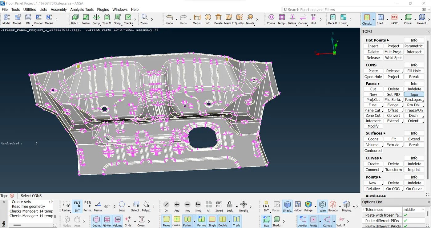
- Topological Activity :- Topology refers to the connectivity of different faces and features within a geometry, forming CONS. CONS come in three types: SINGLE CON (Red), DOUBLE CON (Yellow), and TRIPLE CON (Cyan Blue). Before mid-surfacing, the model should consist only of double cons for better analysis results. Feature lines represent boundary CONS, while other CONS are Construction Lines generated during component modeling. Construction lines can be adjusted to improve mesh flow, but feature lines should be preserved to maintain the geometry's design features. For avoiding element failure, certain feature lines can be modified if their length is less than the minimum element size. In the topological activity, orienting faces using the Faces → Orient option is the final step. Grey surfaces denote the positive direction, and Yellow surfaces represent the negative direction. Inconsistent faces with both Grey and Yellow colors can be fixed by assigning one side to be Yellow and the other side to be Grey. This ensures a consistent model ready for further analysis.
- Mid-Surface Generating :-
Mid-surface Generation in ANSA: The mid-surface represents the middle layer of a component with uniform thickness. It can be generated using two methods in ANSA:
-
Faces → Offset: Manually generates the mid-surface by offsetting each face using the Faces → Offset command. Stitching the faces together with Faces → Topo is necessary to create double cons where surfaces meet. Care must be taken to ensure proper orientation by using Faces → Orient after generating the mid-surface.
-
Faces → Mid-surface → Skin: Automatically generates the mid-surface by deleting original faces. Faces are colored red and green, and the thickness region is blue. Neighboring red and green faces must be avoided. This method is preferred for models with a high number of faces to save time, despite a slightly higher chance of errors compared to the manual approach.
- Measurement of thickness: Assessment of the distance between two opposite surfaces or boundaries of an object or material.
-
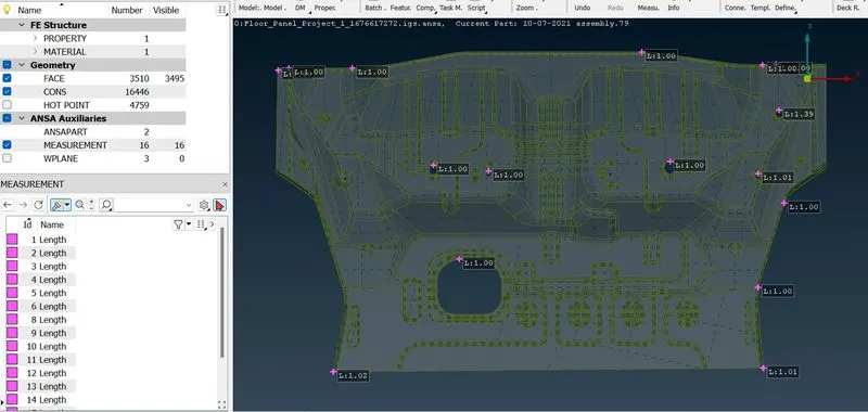
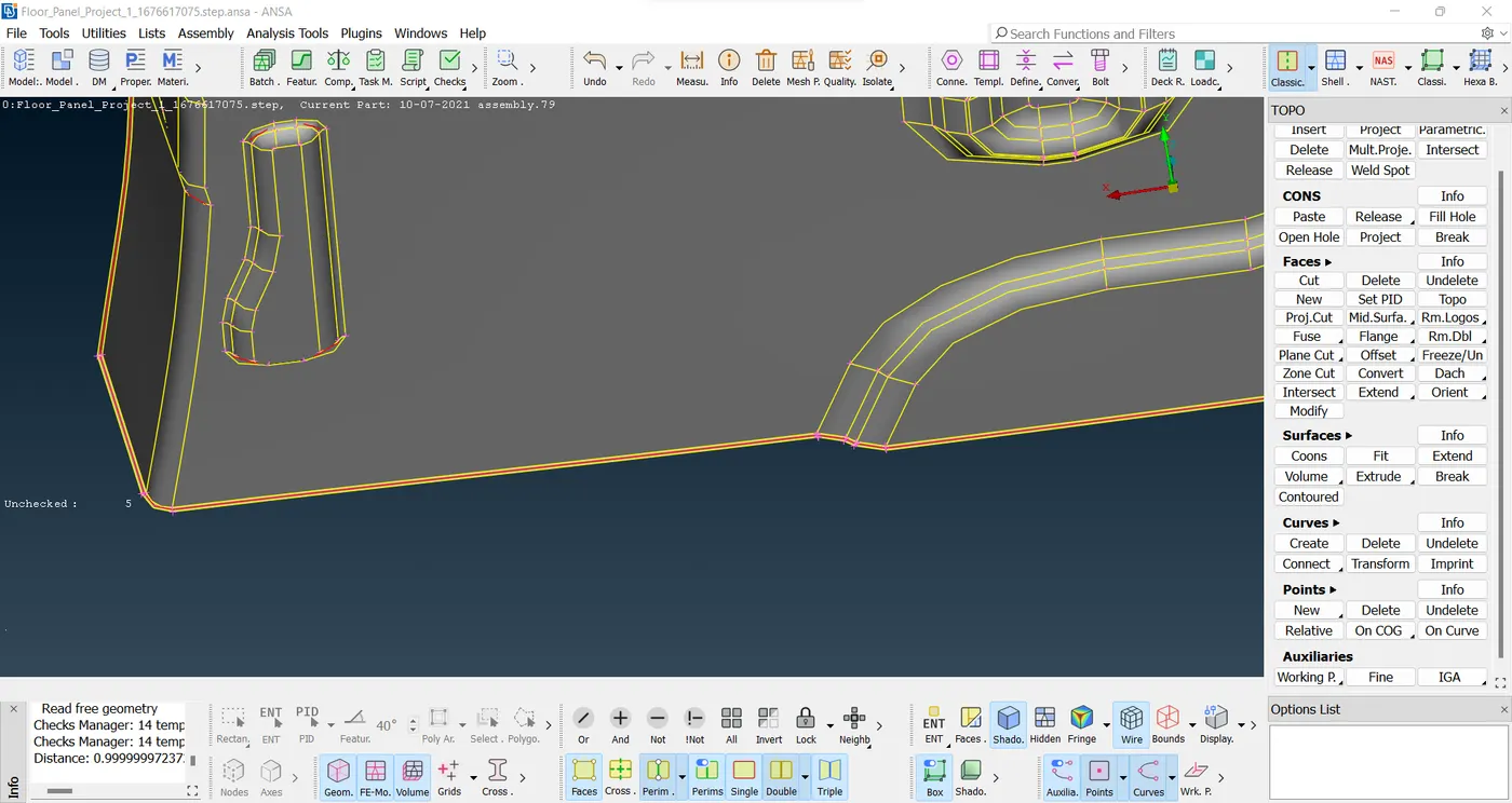
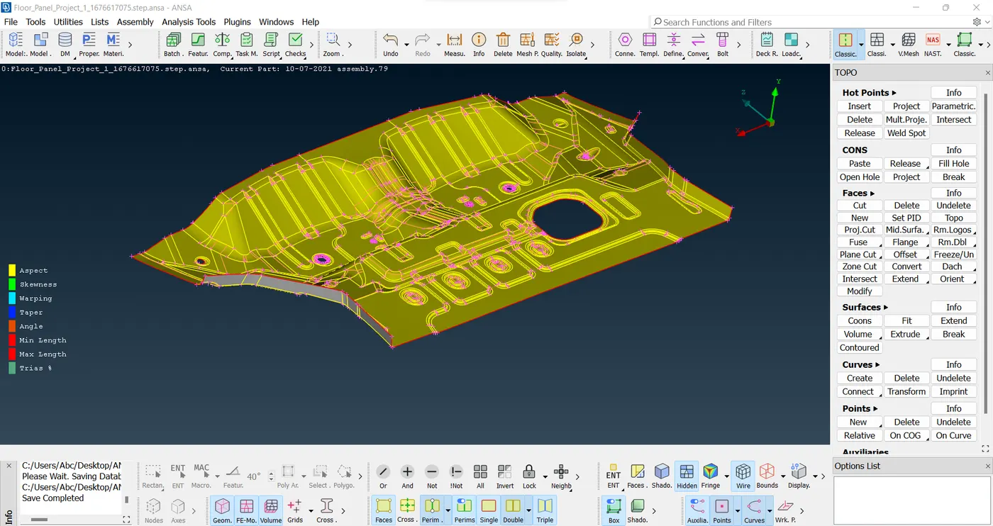
- Set PID :- PID (Property Identification Number) is used to assign material and thickness to the model. To set PID, use Faces → Set PID, then open the properties window by middle-clicking. Create a PSHELL dialog box, enter the desired thickness and click OK. Next, specify material properties such as Young's modulus, Poisson ratio, and density. Apply the material to the PID by right-clicking on it and selecting "Apply." Verify the application by switching to PID mode from ENT mode in the Drawing Styles bar. The model's color will reflect the assigned properties.
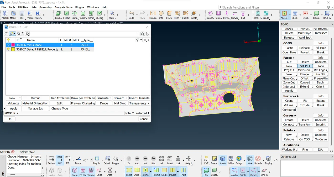
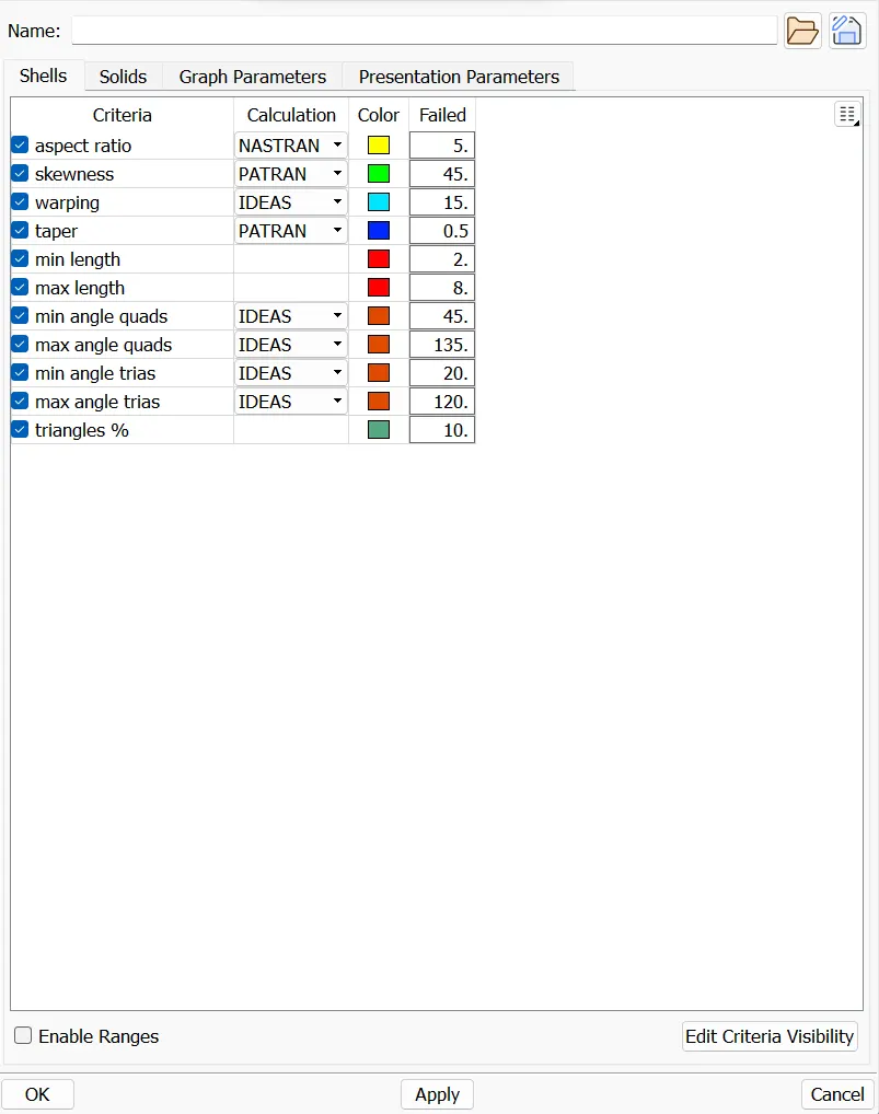
- Mesh Parameter and Quality Criteria :- The mesh quality is user-defined, tailored to specific applications. To achieve desired mesh quality, two main aspects must be considered: Mesh Parameters and Quality Criteria. Mesh Parameters, such as average element size, minimum element size, maximum element size, and mesh order, can be defined in the Utilities Bar. Additionally, Mesh Quality Criteria can be set from the Utilities Bar or by pressing F11. Below are the quality criteria inputs for our mesh and put in this model quality criteria given below.

- Meshing Generation :- Mesh generation involves discretizing the entire model into smaller elements. In 2D meshing, two types of elements are used: Quadrilateral (Quad) and Triangular (Tria) elements. Quad elements have four nodes and are considered ideal, with deviations measured against a square element.They are structured, offering shorter processing time and higher accuracy, making them preferable over tria elements.
- Meshing :-
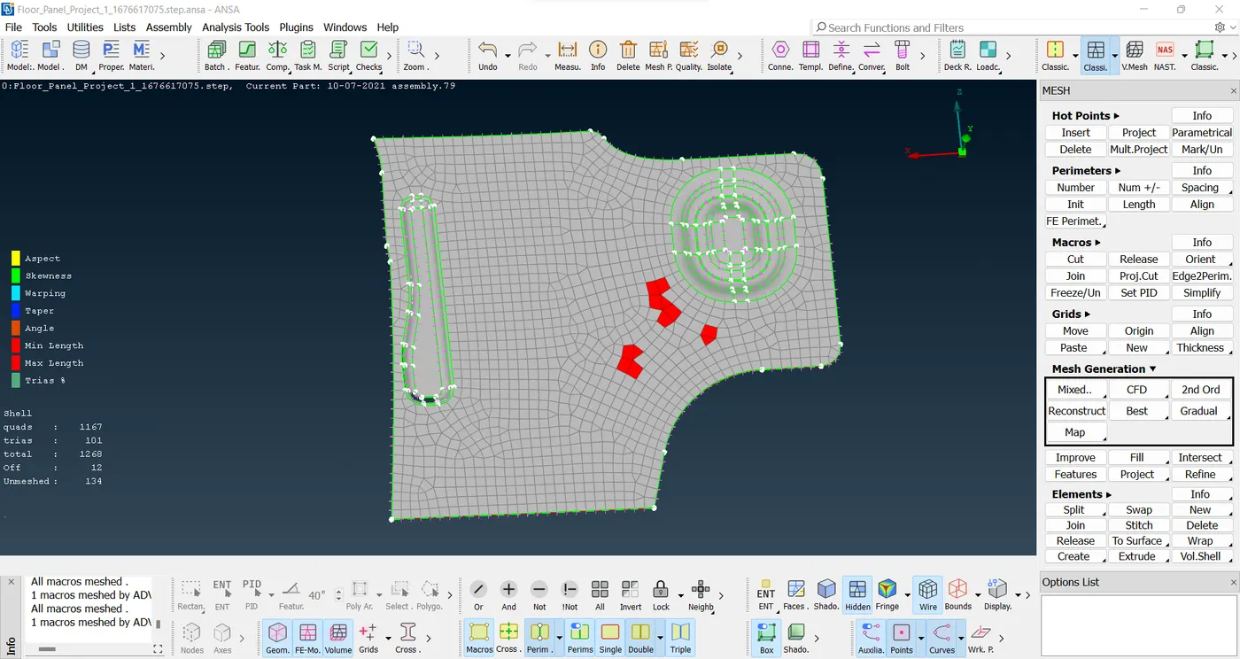
The mesh is generated for the entire model by following the above-mentioned steps.
Steps to create a proper mesh for this model:
-
The meshing process starts from the model's center and moves outward to eliminate triangular elements.
-
To minimize triangular elements, the outer hood surface is discretized into rectangles.
This approach ensures a well-structured mesh with reduced triangular elements for improved accuracy and efficiency.
-
- Meshing Flow and Mesh Quality Improvement :-
While ANSA facilitates easy mesh generation, the resulting mesh often contains numerous elements failing to meet the Mesh Quality criteria and may include unwanted Triangular elements. To achieve superior mesh quality and flow, several crucial steps can be taken. The following options in ANSA are utilized to enhance mesh quality:
- Reconstruct
- Smooth
- Split, Swap, Join, Paste
- Changing Nodal Numbers
- Edge2Perimeter
These options are applied to the entire model to generate a refined mesh with improved Mesh Quality and Flow, ensuring better accuracy and performance.
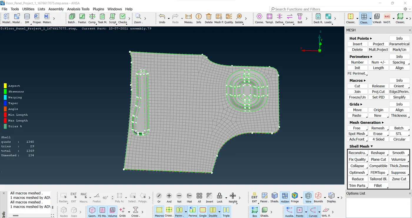
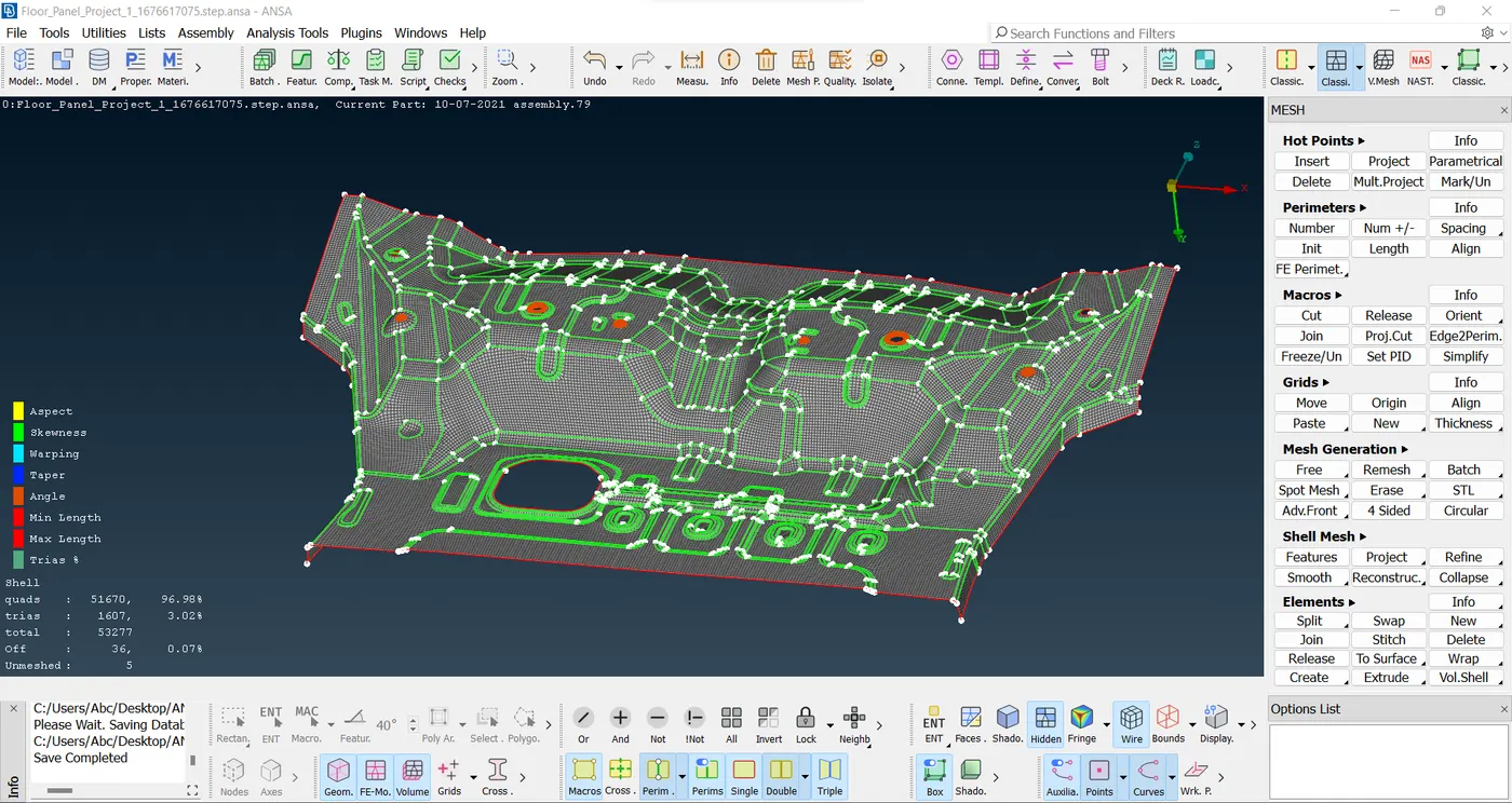
- Final Model
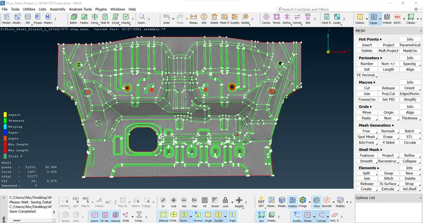
- Result :-
Optimizing Geometrical Model for Preprocessing:
- Ensure a geometrically error-free model.
- Understand construction and feature lines without affecting the model's features.
- Perform topological activity while preserving the model's integrity.
- Extend and join surfaces, and generate new surfaces if needed.
- Generate a mesh for the model.
- Enhance the model's features and mesh element quality.
- Utilize options like Align, Paste, Nodal+-, Element Delete, New Element, Reconstruct, Smooth, etc., to improve Mesh Quality and Flow.
NOTE :- The (.ansa) file is not uploading. that's why I given the link of the data.
https://drive.google.com/file/d/1D79ABAGr5K54_EnYmbaoMeNdryiPhd3q/view?usp=drive_link