Week - 4 - 2D meshing for Plastic components
2D Meshing of Plastic component (Bottle Cap) Challenge
Objective-
Meshing of provided plastic component (Bottle Cap) and achieve stated Quality criteria using ANSA. This challenge gives the idea of meshing the plastic component, achieving quality criteria, modifying mesh.
CAD Model Image-
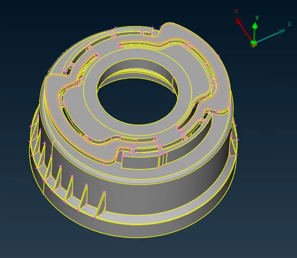
Fig.-1
Procedure-
- Import the provided CAD Model and analyze it properly.
- Now go to the checks manager and check the geometry. Geometry checks provide feasibility to repair the geometry. Just execute the Check manager & fix all the errors as shown in fig. 2.
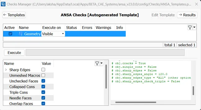
Fig.-2
- Now measure the thickness of the component at different places using measure tool. In this component thickness is different at different places. So, it’s a plastic component.
- Now, go for extracting the midsurface. For extracting the midsurface, there are different methods such as automatic midsurface and offset manual method.
After extracting the midsurface, there may be possibility that some uneven surface may form, so cure them using commands such as coons, new faces, etc.
So, after doing all these, run the geometry check manager.
The midsurface for bottle cap is as shown in fig. 3.
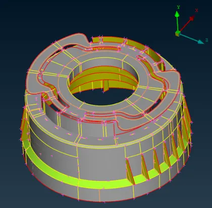
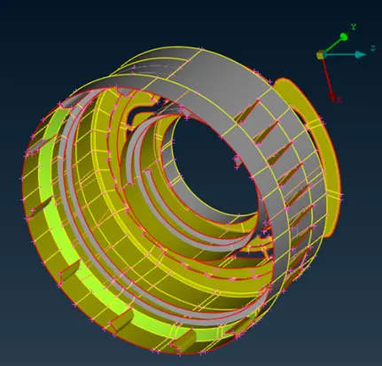
Fig.-3
- Now, analyze the mid-surface properly, if any surface or edge is missing fix it and proceed for meshing.
- For meshing, set the meshing parameters needs to be set and it can be set through met parameters tab, as shown in fig. 4.
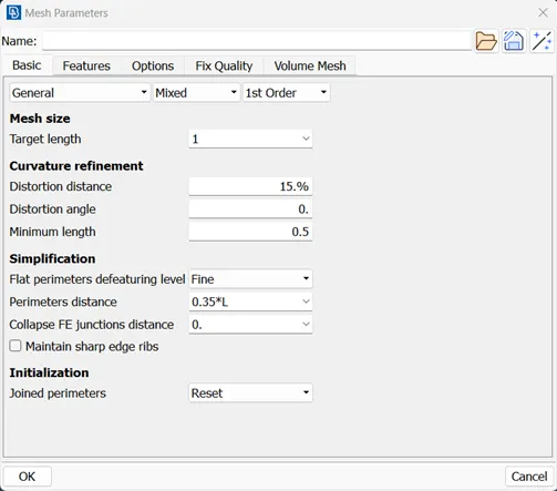
Fig.-4
- For meshing and to check the mesh quality criteria is needed. Mesh quality criteria is to be set through mesh quality criteria tab. Set the mesh quality criteria as mentioned in the challenge as shown in fig. 5.
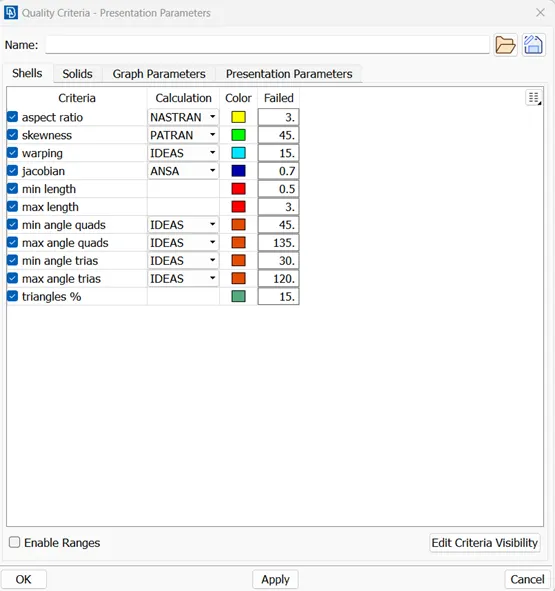
Fig.-5
- Now, mesh the object using best command. To maintain the proper mesh flow lines and achieve mesh quality, use the option commands such as Reconstruct, Improve, Smooth commands.
- After meshing, go for quality checking, enabling the hidden tab as shown in fig. 6.
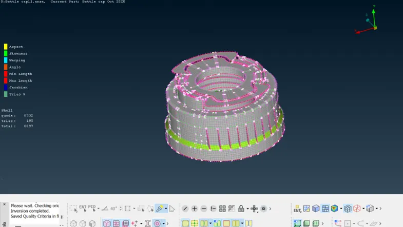
Fig.-6
- If suppose during quality checking some of the elements failed to achieve the quality criteria, cure them using commands, split, swap, join, collapse, move, paste, etc. and by remeshing particular surface quality criteria can be achieved as shown in fig. 7,8 & 9.
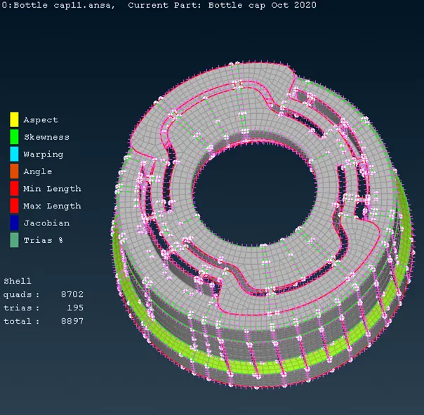
Fig.-7
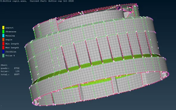
Fig.-8
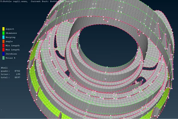
Fig.-9
- Since, this is a plastic component, it is having varying thickness. To assign thickness, different surfaces have to be moved in different PIDs, which can be done using command Set PID.
- Now, create the PIDs with different thicknesses as shown in fig. 10.
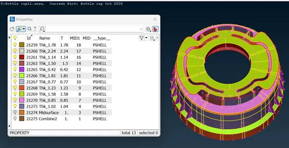
Fig.-10
Result-
As per the given criteria, models have been meshed.