Week 9-Creation of 1D Connectors Challenge
Report on Connectors between two components
Objective-
Meshing of given CAD Models as per stated Quality criteria and provide stated connectors using Hypermesh.
CAD Model Image-
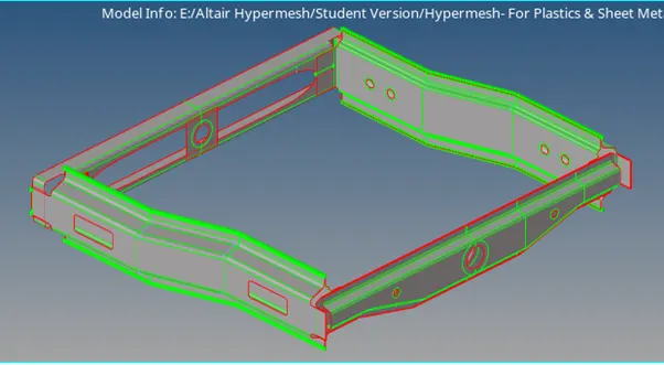
Fig.-1
Procedure-
- Import the provided CAD Model and analyze it properly. If there exist any problem in model through Quick Edit & surface edit panel, rectify the problem and prepare the model for 2D Meshing so that minimum element size length can be achieved.
- Now define the mesh quality criteria as shown in fig. 2.
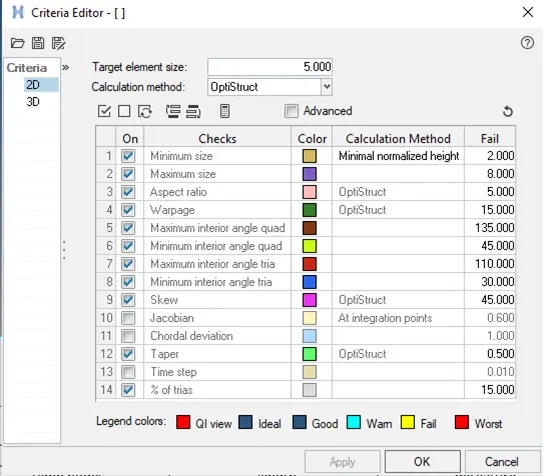
Fig.-2
A. Seam-Quad (Angled+Capped+L) between Right Rail-2 & Front Truss-1-
3. Mesh the Righ Rail-2 & Front Truss-1 components with element size 5 as shown 3.
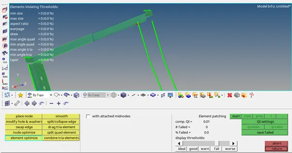
Fig.-3
- Now go to the connectors----Seam and select the nodes and the components between which the connector has to be provided. Select type of the connector as Angled+Capped+L as shown in fig. 4.
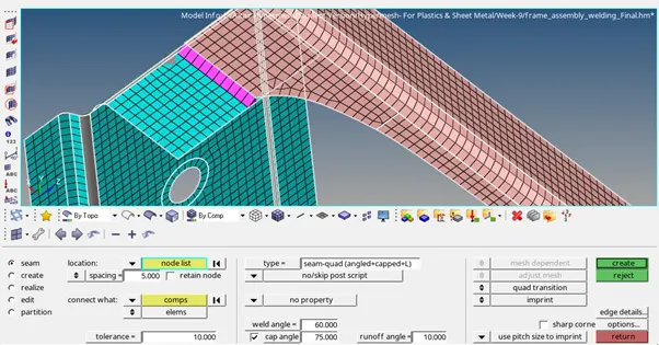
Fig.-4
B. Quad Elements between Left Rail-2 & Front Truss-1-
5. Mesh the Righ Rail-2 & Front Truss-1 components with element size 5 as shown 5.
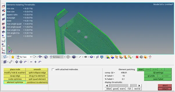
Fig.-5
- Now go to the connectors----Seam and select the nodes and the components between which the connector has to be provided. Select type of the connector as Quad as shown in fig. 6.
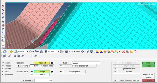
Fig.-6
C. Spot Weld between Front Truss-2, Front Truss-1 & Right Rail-1-
7. Mesh the Front Truss-2, Front Truss-1 & Righ Rail-1 components with element size 5 as shown 7.
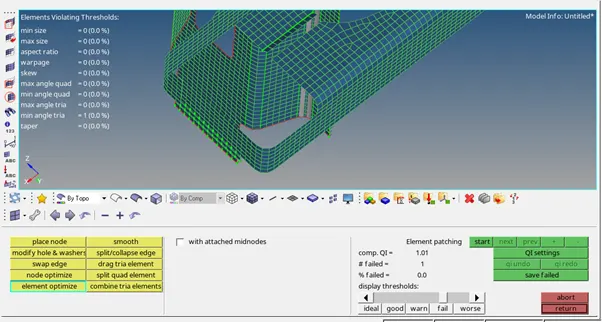
Fig.-7
- Now go to the connectors----Spot and select the nodes and the components between which the connector has to be provided. Select number of layers as 2 & weld dia to be 5. Here two components has to be selected separately as shown in fig. 8 &9.
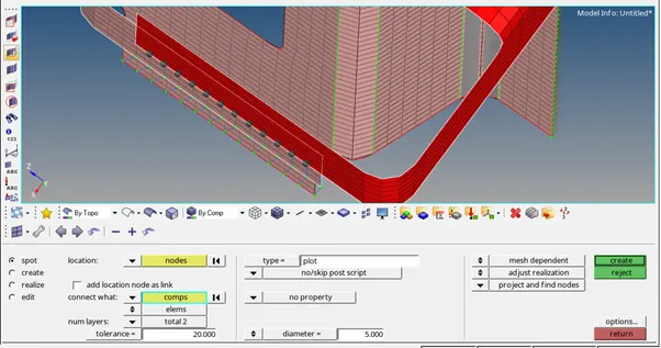
Fig.-8
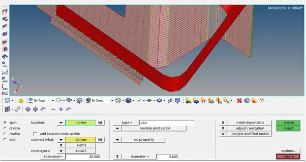
Fig.-9
D. Hexa (Adhesive) between Front Truss-2, Front Truss-1 & Left Rail-1-
9. Mesh the Front Truss-2, Front Truss-1 & Left Rail-1 components with element size 5 as shown 10.
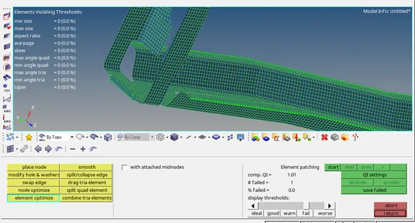
Fig.-10
- Now go to the connectors----Seam and select the nodes and the components between which the connector has to be provided. Select type as Hexa (Adhesive). Here two components has to be selected separately as shown in fig. 11.
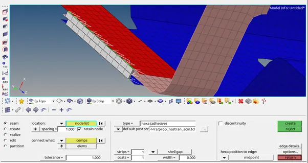
Fig.-11
E. Bolt Connection between Rear Truss-2 & Right Rail-2-
11. Mesh the Rear Truss-2 & Right Rail-2 components with element size 5 as shown 12.
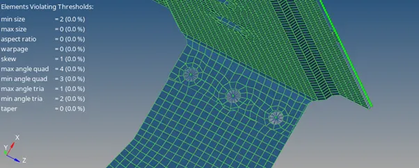
Fig.-12
- Now go to the connectors----Bolt and select the nodes and the components between which the connector has to be provided. Here select the tab create hole if none as shown in fig. 13.
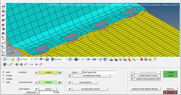
Fig.-13
F. Bolt Connection between Rear Truss-2 & Left Rail-2-
13. Mesh the Rear Truss-2 & Left Rail-2 components with element size 5 as shown 14.
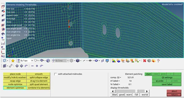
Fig.-14
- Now go to the connectors----Bolt and select the nodes and the components between which the connector has to be provided. Here select the tab create hole if none as shown in fig. 15.
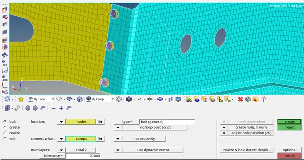
Fig.-15
G. Spot Weld with Rigid Connection between Right Rail-1 & Right Rail-2-
15. Mesh the Right Rail-1 & Right Rail-2 components with element size 5 as shown 16.
Fig.-16
- Now go to the connectors----Spot and select the nodes and the components between which the connector has to be provided. In the type select the rigid as shown in fig. 17.
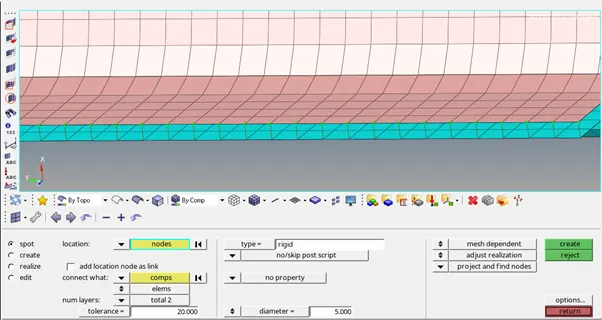
Fig.-17
H. Spot Weld with Rigid Connection between Left Rail-1 & Left Rail-2-
17. Mesh the Left Rail-1 & Left Rail-2 components with element size 5 as shown 18.
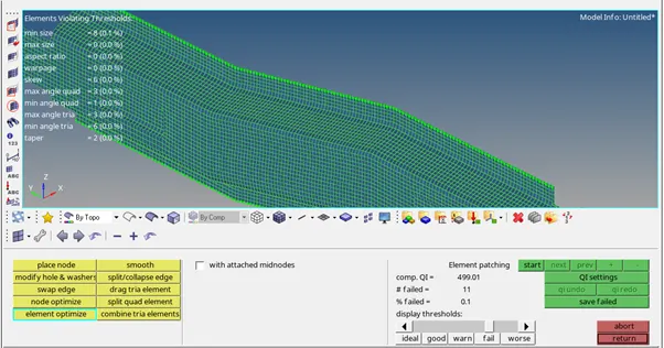
Fig.-18
- Now go to the connectors----Spot and select the nodes and the components between which the connector has to be provided. In the type select the rigid as shown in fig. 19.
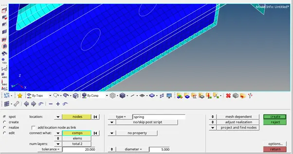
Fig.-19
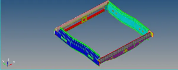
Fig.-20
Result-
As per the given criteria, models have been meshed and stated connectors have been provided.