Week - 4 - 2D meshing for Plastic components
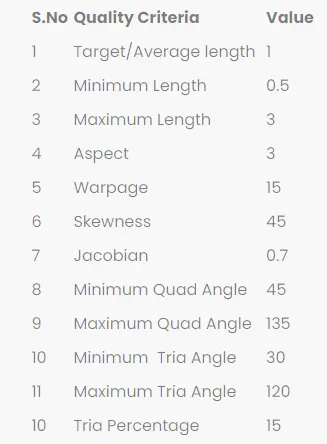
Aim: For the given Plastic Bottle Cap model, check for the geometrical errors and take the mid surface by suitable mid surfacing techniques. PID and Thickness assignment has to be done for all the mid surfaces. Mesh the same with the given element Quality criteria. (Refer to the table below for the Quality criteria)
Quality values:
Methodology:
The methodology for the given element is as follows:
- Import geometry and delete undefined property.
- Perform a Geometrical clean up
- Extraction of Mid surface
- Giving the Quality Criteria.
- Creating a mesh
- Draw shell as solid
Procedure:
- Open the ANSA software and then import Bottle Cap model into the graphical area. Click the model browser from the tab present at the top of the window or press F12 to display the database on the left side of the graphic area at the top to select the component to be worked on.
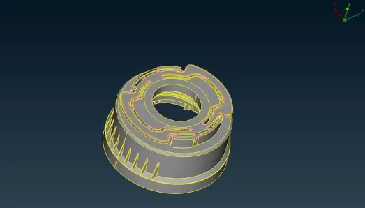
- Click on the CHECKS tool from the dropdown list select the Geometry option.
- Upon entering into the Geometry window, check on the Active button and change the option for the Execute on option to Visible and click on the Execute button. The errors present in the model will be displayed. Now click on the errors one by one and right-click and select the option Fix which means the error will be automatically fixed by Ansa if possible and if it is not possible it needs to be fixed mannually. In this way clear all the errors before taking the midsurface frrom the given model. There are two ways to extract the midsurface from the given component, extracting the midsurface manually i.e., using the Offset option and the other by using the automidsurface i.e., using the Midsurface option. Both tools Offset and Midsurface present in the Faces tools in the Topo mode.
- Use the Offset tool to extract the midsurface for a better experience of workking on the component. Before using the Offset tool, measure the thickness of the Bottle_cap model. After measuring the thickness of the Bottle_cap component use the Offset option to extract the midsurface from the given component.After extracting the midsurrface from the given component try to mesh the extracted midsurface.
- Use the Offset tool to extract the midsurface from the given component where it is possible. But there are somme surfaces on the component like Ribs, Threads, Teeth etc where the Offset option cannot be used. So there is a way to extract the midsurface from these surfaces.
- Threads are in Trapezoidal shapes it is impossible to extract the midsurface using Offset option.
- So we use the Middle option in the Curves to create a curve in the middle of two selected CONS. First, click on the Middle in Curves, then select the first and second Cons on the Thread and then Middle-click to confirm the curve. The Fine option in the Auxiliaries can be used to click multiple times over purple coloured curves to increase the resolution on the curve. By doing this, the curve will form a proper shape.
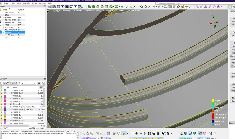
- Middle curve projected in the normal direction to the base Midsurface by using the Project option in the CONS by selecting the Curve press Middle-click and then selecting the Face or the Midsurface where it is to be attached and then Middle-click to confirm it. After projecting the Middle curve to the side Midsurface, create a surface by using COONS in the Surfaces tools.
- Click on the COONS option in the Surfaces tools and then select the Middle curve and then select the Double Cons projected onto the side Midsurface and Middle-click to confirm the surface.
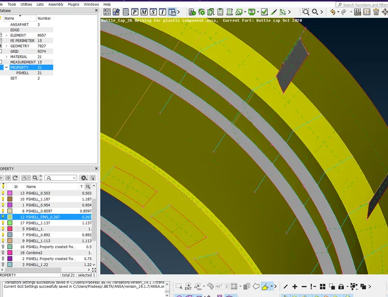
- Triple Cons formation after the surface creation (its in negliance criteria). It is formed due to the sharing of the three edges over there, which is common. The same procedure can be repeated for Ribs and all other complicated surfaces where we cannot extract the midsurface normally.
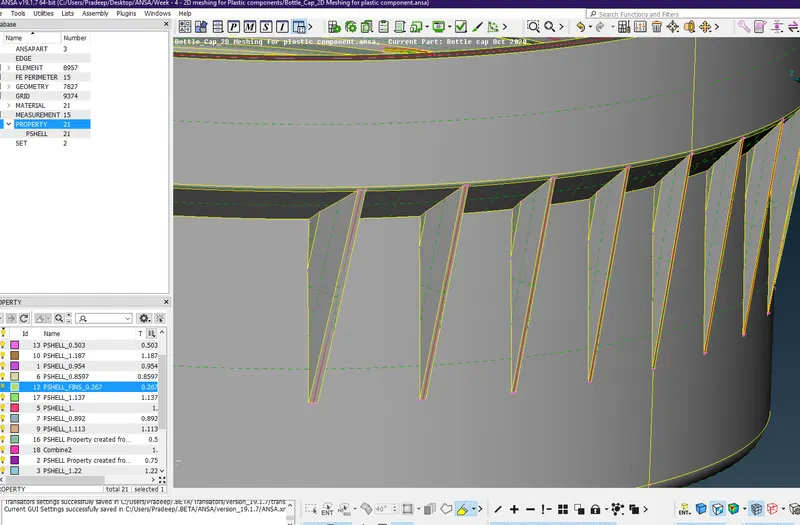
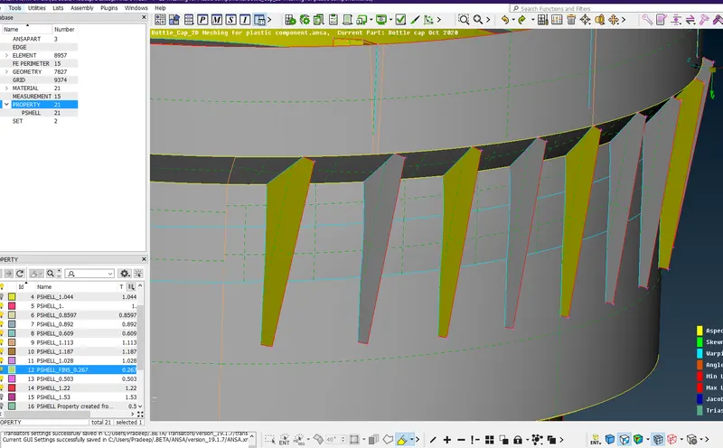
- For Teeth, Middle option in the Faces tools to extract the midsurface. Click on the Middle option in that select the Single-Mode option and select the first face and click on the middle-click and then select the second face on the other side and click on the middle-click to confirm.
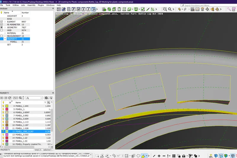
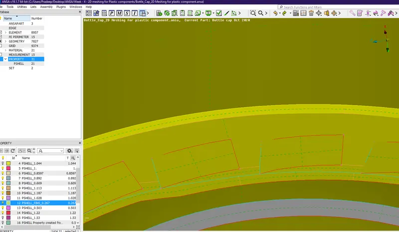
- After extracting the Midsurface try to extend it by using the Extend option in the Faces tab. Select the Single CON and middle-click and select the face to which it needed to be extended and middle-click once after confirmation to finish it. A Triple CON will be formed after the extension of the Single CON to the surface because of the connection of the 3 surfaces.
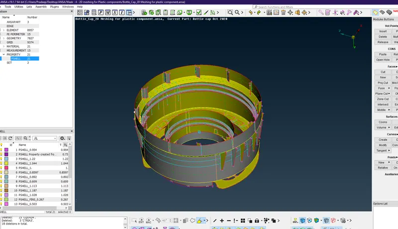
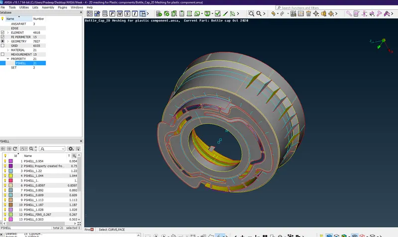
This figure shows the total mid-surface generation of BOTTLE CAP MODEL
- After extracting the midsurface of all the surfaces, try to apply the given target element length on the midsurface. To apply the length, change Mesh mode from Topo mode, select the Length option in the Perimeters, select the whole midsurface, enter the given target element length value and click the middle-click on the mouse to confirm the task.
- After applying the target element length on the midsurface meshing process started. Keep the Mesh mode as it is and click on the Best Mesh in the Mesh Generation. Select a face on the midsurface and middle-click to generate the mesh. The mesh generated on the selected face, if the mesh pattern was not good try to reconstruct the mesh by using the Reconstruct tool in the Shell Mesh tools.
- If there are any mesh elements failing for the given quality criteria, try to make them not fail by using the different tools.
- In the Mesh mode and at the bottom there are the Elements tools present. In these Elements tools, there are options like Split, Join, Swap etc are present use these tools to clear the mesh quality manually. For example, if any less number of elements failing for the Minimum Elements Size try to clear them manually by using the Split option in the Elements tools by splitting the elements and also to clear the Trias in the mesh generated by splitting them and also by joining them by using the Join tool.
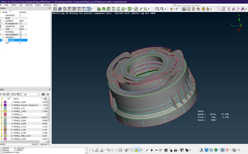
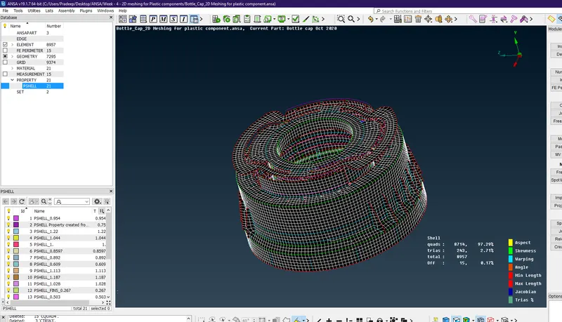
- There might be some Failed elements near Triple CONS or at smaller regions that are bounded by two Triple CONS. set it OFF elements as it is if not possible to solve. After splitting the elements, the mesh pattern will be disturbed and then use the Smooth tool in the Shell Mesh tools to smoothen the disturbed mesh pattern. If there are a huge number of elements that are failing for the quality try to use the Reconstruct tool present in the Shell Mesh tools.
- There are a lot of surfaces present in the component and try to apply the Thickness for each of the surfaces individually because of the varying thickness of the different surfaces. To Assign thickness for the varying thickness ribs, Split the surface into multiple surfaces by using the “CUT” command and give different thickness values such that it captures varying thickness components in the best possible way.
- Use the Set PID tool to apply the Thickness by creating a Property ID. Click on the Set PID tool and select the whole surface because the total surface is of the same thickness, a pop-up window will be displayed in that enter the thickness value and select a proper colour in the Colour-edit and click on the OK button. If there is any varying thickness in the given model then property applied should be different for different surfaces.
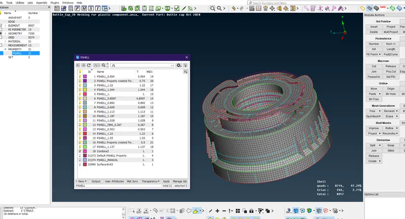
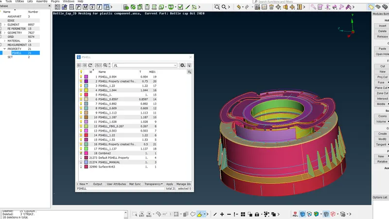
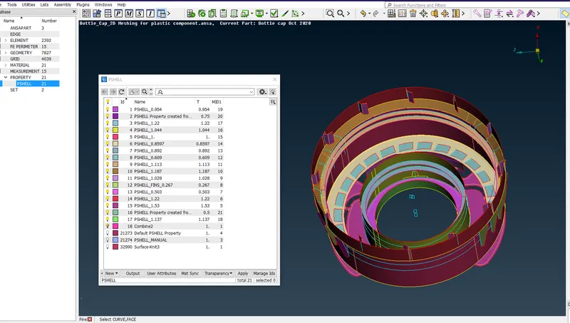
- Switch on the PID mode which is at the bottom of the window in order to look if the property has been applied properly or not (the above two images shaow that how it looks).
Conclusion:
Initially geometric clean up is done. Midsurface have been extracted for diferent surfaces in the given model. Meshing has been generated on the extracted surface, Quality has been checked within the given quality criteria values by and also the Thickness has been assigned to all the extracted Midsurfaces