Week - 4 - 2D meshing for Plastic components
For the given Plastic Bottle Cap model, check for the geometrical errors and take the mid surface by suitable mid surfacing techniques. PID and Thickness assignment has to be done for all the mid surfaces. Mesh the same with given element Quality criteria. (Refer the table Below for the Quality criteria)
|
S.No |
Quality Criteria |
Value |
|
1 |
Target/Average length |
1 |
|
2 |
Minimum Length |
0.5 |
|
3 |
Maximum Length |
3 |
|
4 |
Aspect |
3 |
|
5 |
Warpage |
15 |
|
6 |
Skewness |
45 |
|
7 |
Jacobian |
0.7 |
|
8 |
Minimum Quad Angle |
45 |
|
9 |
Maximum Quad Angle |
135 |
|
10 |
Minimum Tria Angle |
30 |
|
11 |
Maximum Tria Angle |
120 |
|
10 |
Tria Percentage |
15 |
- Representation of a solid part to be extracted by Midsurface. It can be used to generate a finite element shell representation of a solid geometry. It can also be used with sheet metal stampings, molded plastic parts with ribs, and other parts that have thickness clearly smaller than width and length.
- The original geometry that is selected to extract the midsurface from remains unchanged. The new geometry representing the midsurface is placed in a new component collector called Middle Surface, or in the current component, depending on choices made during creation.
- The (variable) thickness for each middle surface is calculated and stored with the surface definition. The auto midsurface and surface pair options are used to create the midsurface.
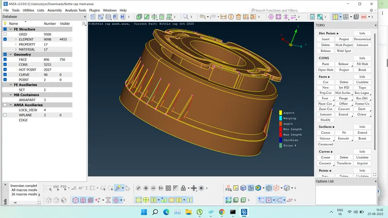
Fig- Main Body
Objective
- perform topology cleanup for geometrical errors
- Creation Midsurface from the 3D Plastic Bottle Cap model
- Assign thickness to them as per surface thickness by creation of Part set
- Meshing of the 2D midsurface model with required quality criteria
Geometry Cleanup
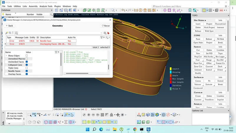
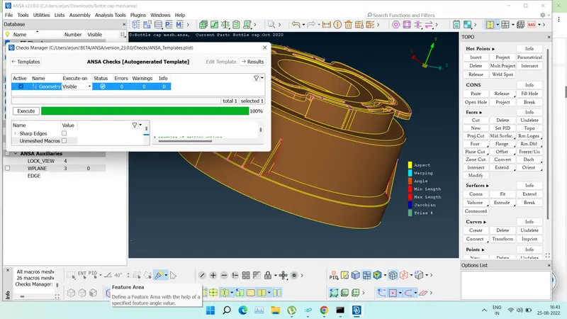
Fig- Geometry cleanup
- In above image, we can see some geometrical errors in the model.
- By selecting and applying “Fix”, we remove the errors and can use it for further process
Midsurface extraction
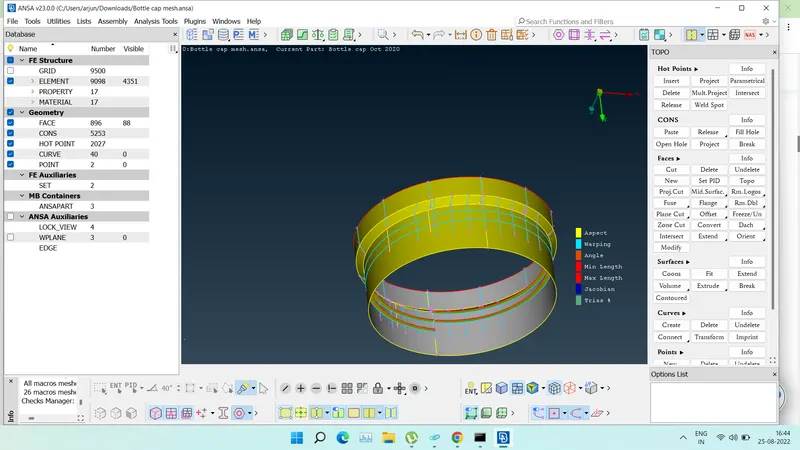
- After geometry cleanup, we can create Midsurface of a component using “Midsurface” option or we can create Midusrface for each different surface manually.
- Here in above image we can see that there are different options as per requirement for different types of components to create midsurface automatically.
- There are options like Skin, Casting, Welding etc. for automatic Midsurfacing.
- But the Plastic Bottle Cap model is very small and very complex, which can generate bad midsurface with automatic options or it may be difficult to create the midsurface automatically for these types of components.
- So we will create midsurface manually for each surface.
- As the thickness varies from surface to surface, we will create the PID for each midsurface or particular group of midsurface and apply the thickness to them.
- To crate midsurface, first step is to measure the thickness, which can be done by node to node distance or if not possible, we can create spots or lines or points, project it on another surface and can measure by selecting them.
- Once we know the thickness, we can select “Offset” under faces option and give the half value according to thickness and create midsurface for selection.
Features
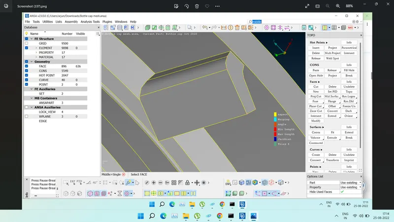
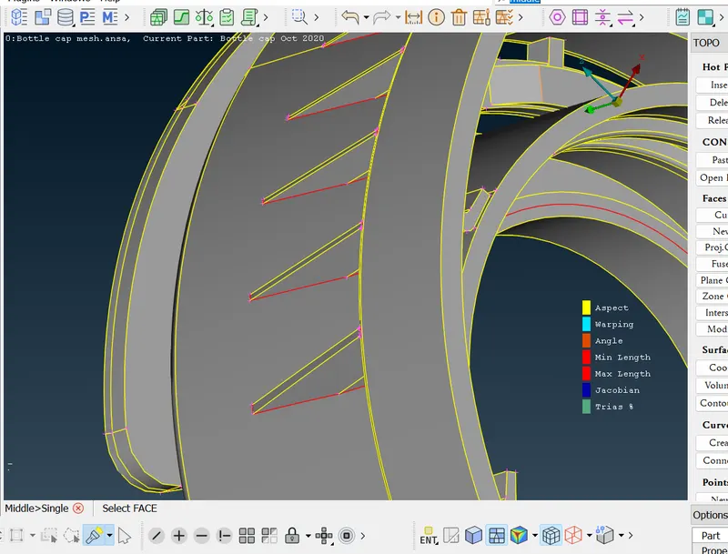
- Here we can see that the feature is varying in thickness.
- So we can use FACES > MIDDLE option for midsurface.
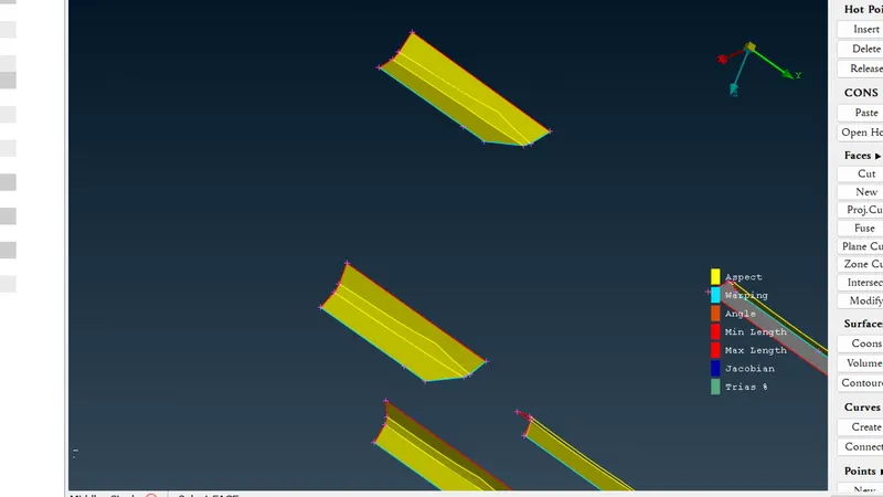
- Also as shown in above image, we can create a middle curve from CURVES > MIDDLE and create a new surface with SURFACE > EXTRUDE > EXTRUDE.
- Here by giving the direction and length of the surface, we can create new surface and later it can be extended to other midsurfaces for connectivity.
Ribs portion
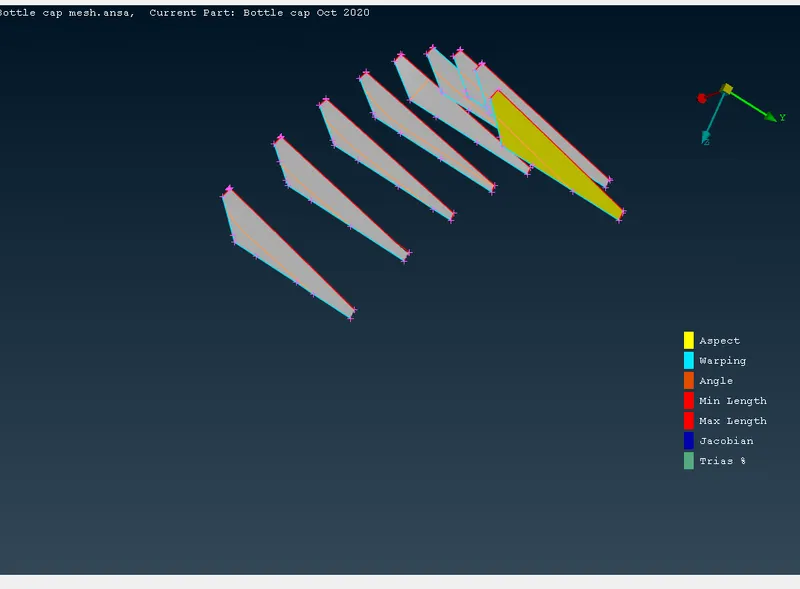
- Here we can see that Ribs are more difficult for creation of midsurface with offset or single middle options as shown in other areas.
- So, here the midsurface is created using FACES > MULTI MIDDLE option.
- By selecting MULTI MIDDLE, we have to give three variable surfaces as RED, GREEN and BLUE.
- With three different surfaces assigned by different colors gives the exact midsurface for the Ribs as shown in above image.
- While creation of midsurface, create PID using SetPID option and give appropriate thickness to relavent midsurface for actual presentation.
Threads
For thread portion we have to take curve middle and create the the curve and project it to the base surface and by creating new surface we can get the midsurface for the thread portion.
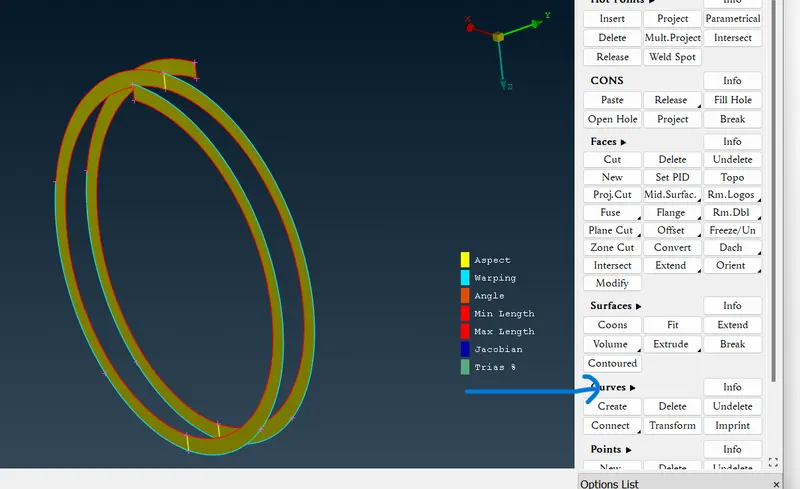
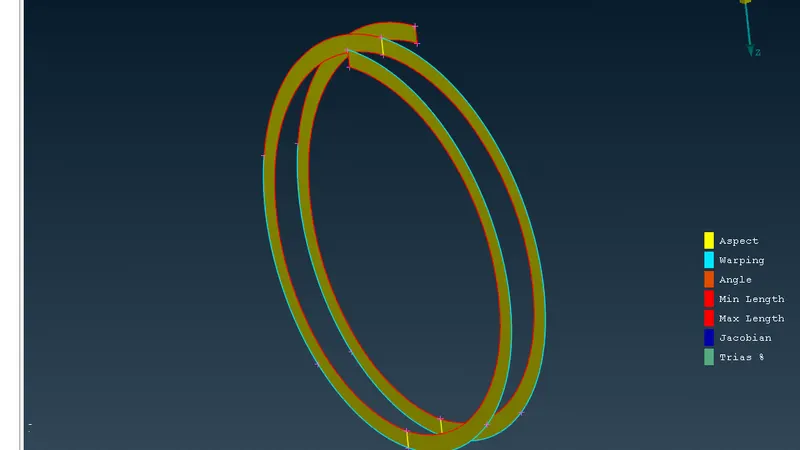
Fig- Curve middle
Teeth
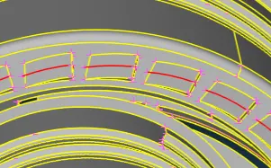
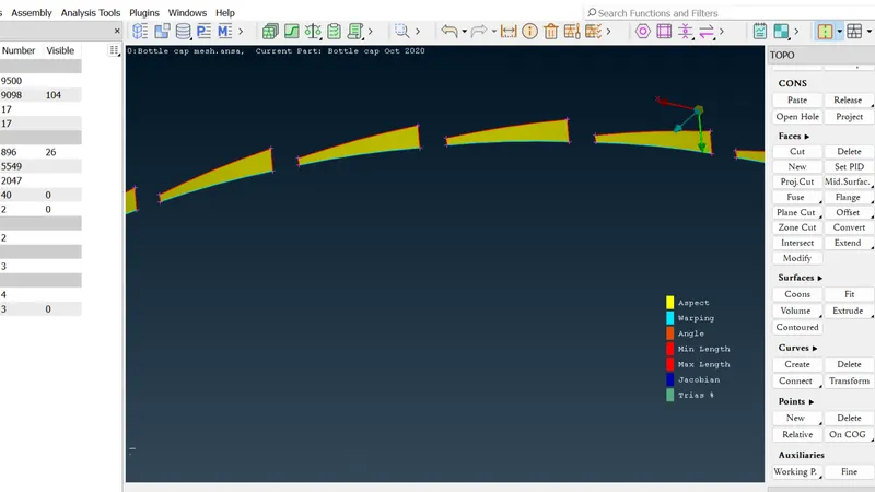
Here as shown in above image, the edge of the teeth is projected to the bottom midsurface and from the middle curve of the face of teeth, and the projected curve, midsurface is created for teeth
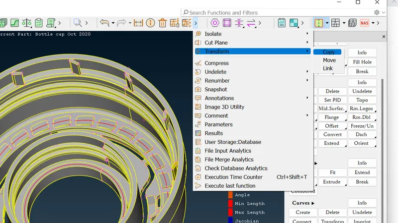
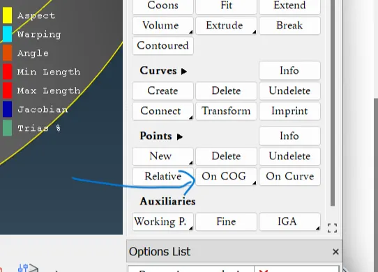
After creating a midsurface for one tooth, we can copy and rotate it in required numbers.
For multiple faces we used transform function to create mltiple faces with the single face
After midsurface creation and applying proper thickness to midsurfaces, make sure that all the cons are properly connected and check the cons either it is single, double or triple.
With topology of cons, we can make sure if there are free edges, two surfaces are connected or three surfaces are in connection.
After completion of all required midsurfaces, we can go for further meshing process.
Meshing:
- Before creating mesh, it is necessary to set required quality criteria parameters for better quality.
- So, the quality criteria for the mesh is as given below:
Qaulity criteria
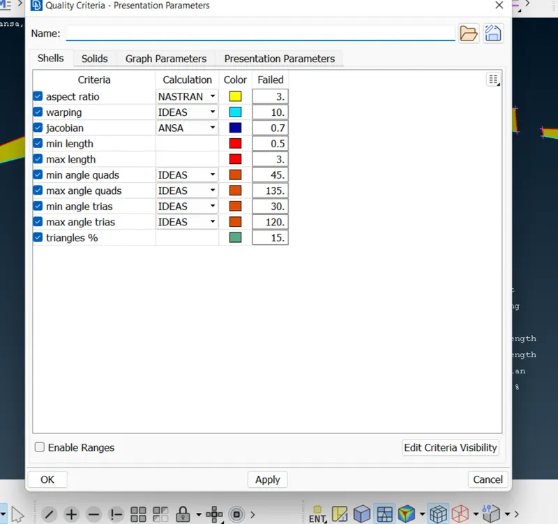
- After setting up the quality criteria, 0we should set the perimeter length as per our mesh size.
- Also it is important to set the target element size as per criteria.
Mesh parameters
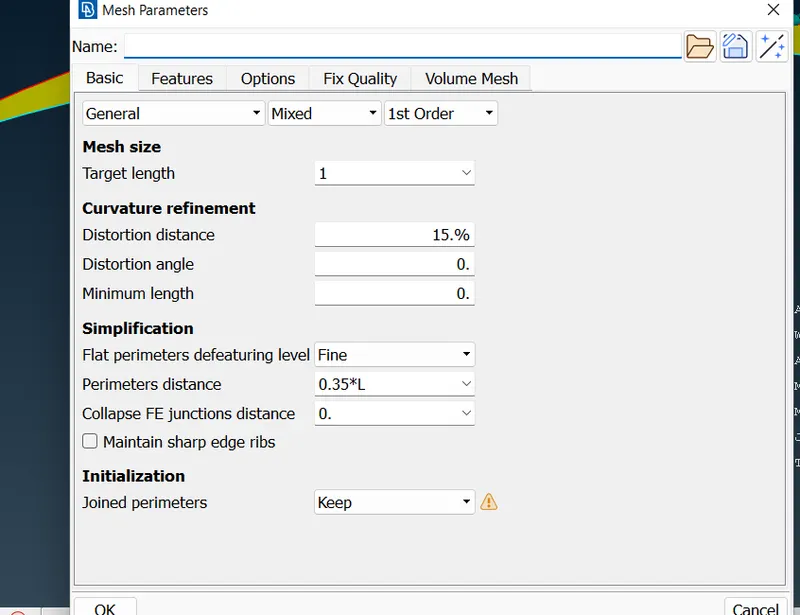
- Here we can see that the perimeter is set to 1 as well as in Mesh Parameters, Target element length also set to 1 with minimum and maximum target length of the elements.
- After setting up all criteria and parameters, we can create mesh by selecting MESH GENERATION > BEST and select all Midsurfaces and apply ok.
- Here we can create mesh one by one on each surface, but it will be very time consuming, so we can create mesh at once for all and then reconstruct the mesh at required areas.
Bad Elements
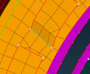
- While meshing, we can see in above image, that there are some bed elements near triple cons.
- At these areas, even reconstructing the mesh is not enough to get good mesh.
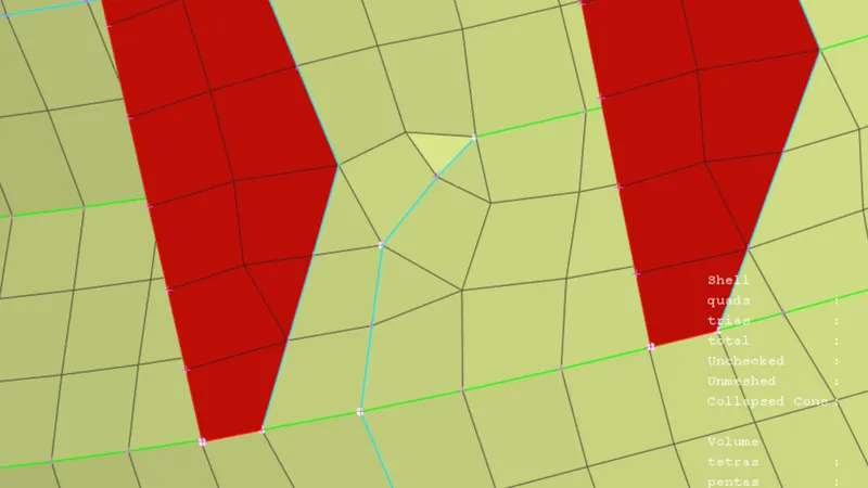
- Where reconstruct does not work, we have to do some modifications which can not affect the results in future.
- So, as shown in above image, we can add some small surface or extend it to boundary or we can cut some surfaces and also we can add double cons or separate it get rid of bad elements and get good quality mesh.
Mesh cleaning
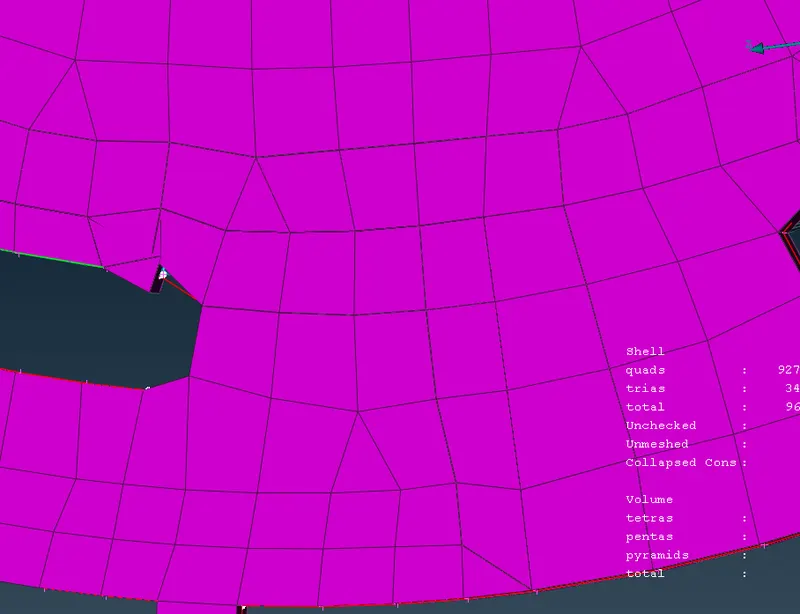
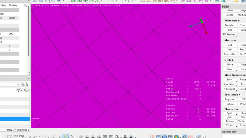
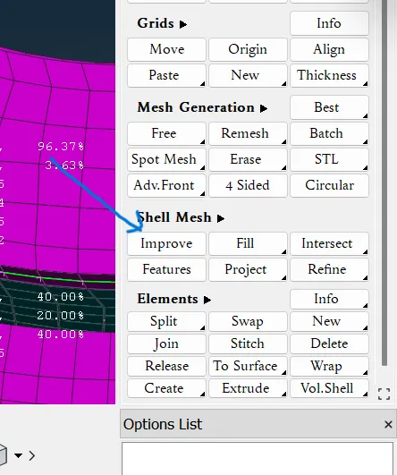
After meshing there were lot of tria elements which shows the bad result. So for resolving that we have opted different manual methods to improve our mesh We use improve option to fine our mesh.
- Now the mesh are generated. check for quality criteria and the failed elements are corrected using tool like smooth,reconstruct,fix quality, move in the mesh module. finally the mesh are generated for the given model.
- Draw shell as a solid
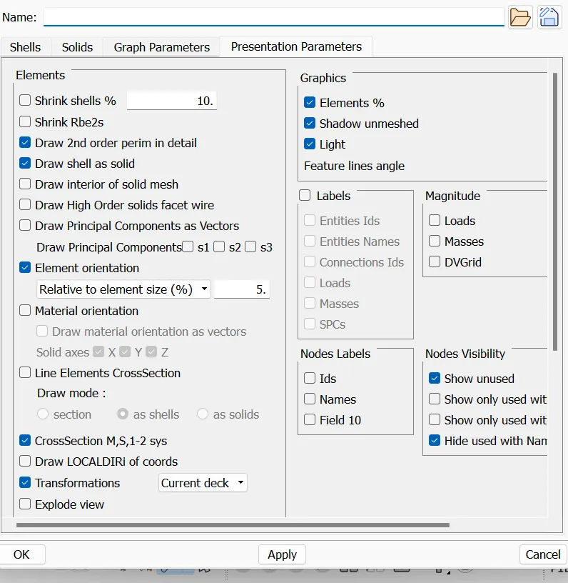
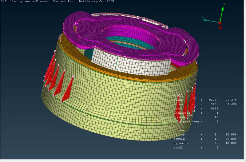
- After completion of meshing, go to QUALITY CRITERIA > PRESENTATION PARAMEERS > DRAW SHELL AS SOLID.
- We can see in above image, with this option we can see all elements in 3D form or as solid.
- Thus the 2D mesh will be displayed as solid mesh according to given thickness of each midsurface.
- Property and thickness assigning
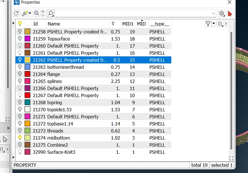
- Now assign the thickness for the midsurfaces. we have some varying thickness surfaces so that we have to create gradual thickness variations under one surface.we can create property easily. select property-new-pshell-assign thickness-assign name.
For each varying thickness of component, we have to assign differrent property according to thickness.
- Comparison between actual geometry and meshed geometry
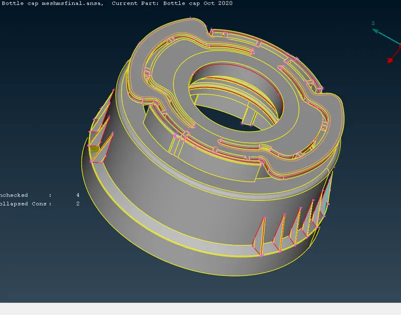
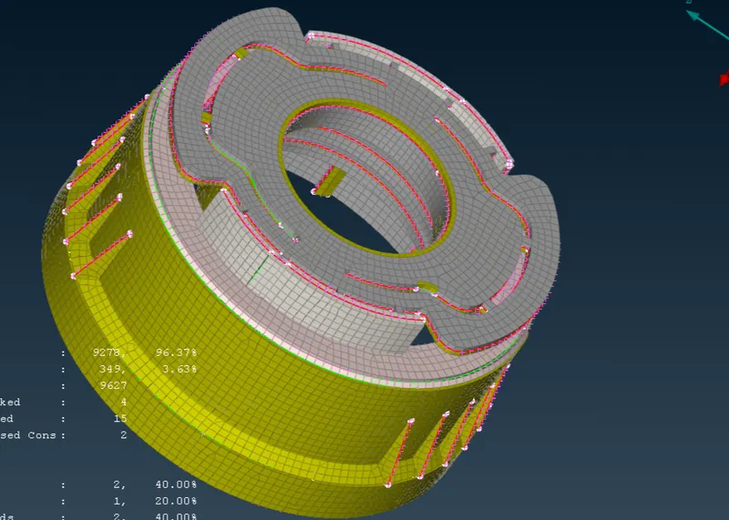
- After that we can check or compare the 3D presentation of 2D mesh and actual 3D model without mesh.
- By comparing them we can know if the meshed model has any mistake or not.
- With that we can make the mesh model more accurate as the 3D geometry and we can get accurate analysis results with good quality mesh.
- Learnings and Outcomes
- From this challange we can get knowledge of creation of Midsurfacing and meshing.
- We can know about the importance of Midsurfacing and also the difficulties while creating midsurface in plastic components where the thickness is variable.
- Variable thickness components must have proper midsurface on which we can create mesh which can give accurate results.
- This project helps in understanding of handling the midsurface at complex areas and position single, double and triple cons.
- Also after Midsurfacing, it is also important to assign thickness properly according to cariable thickness.
- We can create segments and assign different thickness or we can take average thickness as per requirement and complexity of the features.
- While meshing plastic components, it is very difficult to handle triple cons, which should be taken care and splitting of different areas can help in achieving goo quality mesh.
- Here the percentage tria element is 3.63% which is good and we can say that we achieved good quality mesh as per the quality criteria.
- It also important to check after mesh with solid presentation to compare with original geometry.
- Thus, this project helps in understanding of Midsurfacing of complex geometries like Plastic Bottle Cap and also it’s meshing with good quality criteria.