WEEK-4 : 2D MESHING FOR PLASTIC COMPONENTS
PROJECT REPORT
MESHING FOR PLASTIC COMPONENT
Aim :
For the given Plastic Bottle Cap model, check for the geometrical errors and take the mid surface by suitable mid surfacing techniques. PID and Thickness assignment has to be done for all the mid surfaces. Mesh the same with given element Quality criteria. (Refer the table Below for the Quality criteria)
|
S.No |
Quality Criteria |
Value |
|
1 |
Target/Average length |
1 |
|
2 |
Minimum Length |
0.5 |
|
3 |
Maximum Length |
3 |
|
4 |
Aspect |
3 |
|
5 |
Warpage |
15 |
|
6 |
Skewness |
45 |
|
7 |
Jacobian |
0.7 |
|
8 |
Minimum Quad Angle |
45 |
|
9 |
Maximum Quad Angle |
135 |
|
10 |
Minimum Tria Angle |
30 |
|
11 |
Maximum Tria Angle |
120 |
|
10 |
Tria Percentage |
15 |
PROCEDURE :
- The bottle cap model is imported to the ANSA working window. The database interface present at the left top corner contains the details already present in the model like geometry, property, measurements etc.
- NOTE : Any formate like IGS can be imported to ANSA Software , but the surface connectivity may lost so that can be recovered by using TOPO option (TOPO MODULE) .
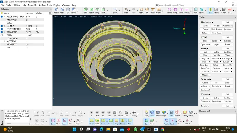
- Next , Step will be cons resolution where the perimeter length can resolved .
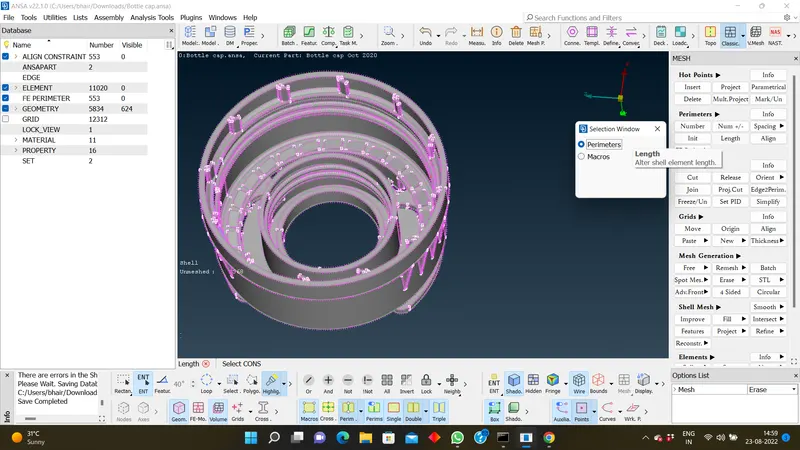
- After importing the cad , the surfaces will not present in same direction , So we can use orient option > TOPO MODULE.
Where the complete surafce wil be in one region . - Then , Errors should be cleared for cad model by geometry check .
- If any errors appear , we can try to fix it automatically or manually .
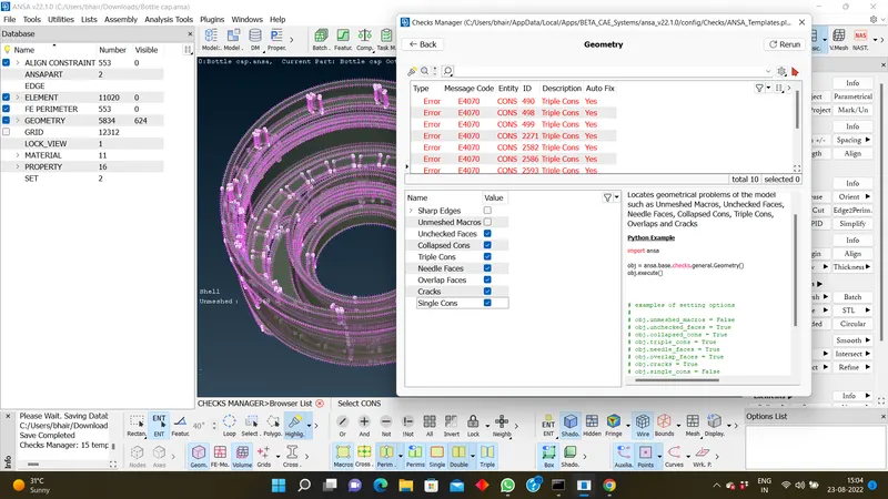
-
- After clearing the Geometry Errors , we can move to creating the mid-surface generation .
- Before , proceeding to the Mid generation . We need to check the thickness of the model (As we know that Plastic component will be having varying thickness through out the component) .
-
Creating the Midsurface for a Plastic component.
- For Extracting the midsurface we will be using the Middle single, Multi and Mid curve methods for varying thickness surfaces.
- While USing the Middle multi and Middle single check the options list and uncheck the unnecessary things.
- For uniform surfaces we will use the offset option.
- We have to make sure the extracted mid surfaces are connected to each other.
- For Connecting the Mid surfaces which were extracted we use the Extend and Intersect options.
- I have used casting option (TOPO>FACES>MID SURFACE>CASTING) Which is an automatic process , but please proceed to use this option in updated version only.
- After generation of mid-surface , the surface will be consist with finite elements but the some of the features like (Ribs, threads,..) may not be captured as parent geometry .
- Next , capturing the failed surfaces and working accordingly to generate the surface as parent geometry .
OPTIONS USED TO CREATE THE FLOW OF SURFACE :
1 . Paste : By using this option , if any elements were not created so we can paste the two nodes of elements .
2 . Align : Used to align the nodes with respective to neighbouring nodes , edges or perimeters ,So the nodes will be aligned to the selected feature respectively.
3 . Align Manager :
This is very important method while creating the good flow of mesh .
Actually , Model consist of areas and perimeters .
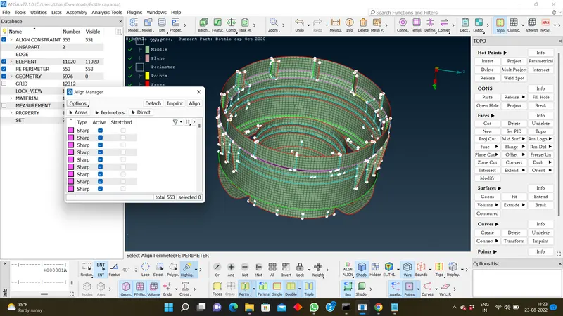
Areas need to align according to the surfaces like if the area consist with single area or flat surface , we
need use plane definition .
Surfaces which were connected with curved surfaces , we need to use Middle definition .
In Perimeters :
Single con : Face definition .
Double con : Imprint definition .
Triple con : Point definition .
We have may option in align manger to align areas or perimeters .
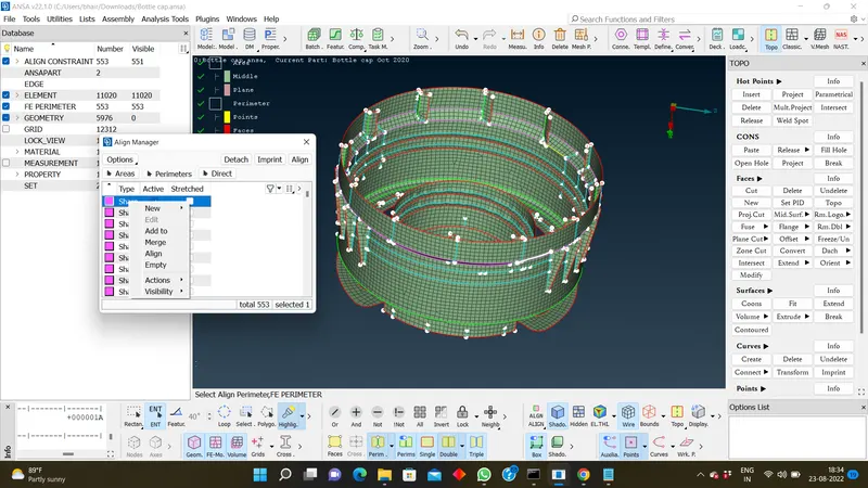
In Areas :
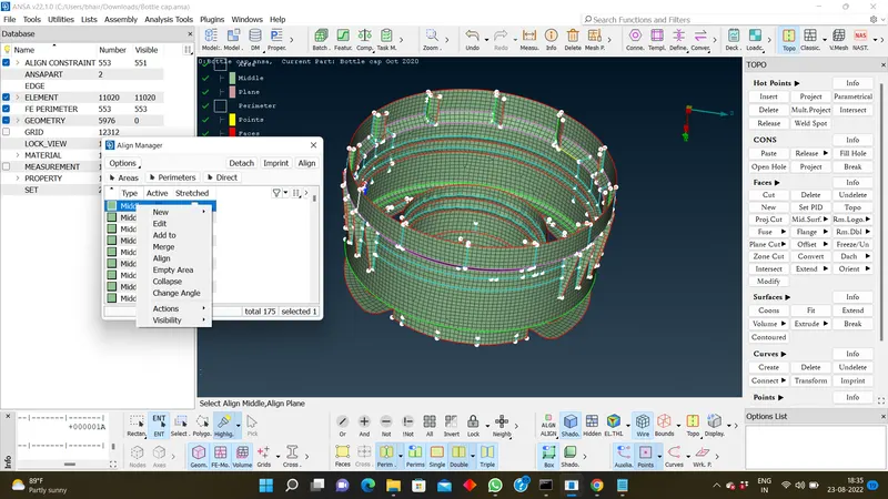
-
Clear the elements which are failing for the quality criteria.
-
Assign the proper thickness for the newly created midsurface.
- We will create n pids based on the n thickness.
- We will be adding the surfaces to those pid’s based on the thicknesses.
- Release the FE from the Geometry.
NOTE :
1. There might be some Failed elements near to Triple CONS or at smaller regions which are bounded by two Triple CONS. Keep those OFF elements as it is if not possible to solve.
2. To copy the mid surface entites for threads, ribs we can use rotate option .
Conclusion:
The extraction of mid surface for the bottle cap model is created and the mesh has done by considering appropriate quality criterias. The mesh parameters has given. The thickness is assigned and also drawn shell as a solid.
MODEL :
https://drive.google.com/file/d/19dPML0gcv7Gl0glBcxdDezmryEYUXcZ_/view?usp=sharing
Thank You !!