Week - 4 - 2D meshing for Plastic components
Introduction
Often the most accurate representation of a part is through the use of shell elements. These elements best represent parts that are relatively thin compared to their overall surface area and typically have a uniform thickness. Shell elements have no physical thickness representation, they are displayed as two dimensional entities whose thickness is simply a numerical value assigned to them. FE Solvers assume the shell element to lie at the middle of the thickness. As that is the case the mesh created on the surfaces needs to lie at the mid-plane of the part. CAD geometry is usually created as either a solid part or a series of faces representing a solid part. Using the middle, Offset, Midsurface etc. Tools in Ansa proper surfaces can be extracted that lie on the mid-plane of the part and can be meshed appropriately.
- Representation of a solid part to be extracted by Midsurface. It can be used to generate a finite element shell representation of a solid geometry. It can also be used with sheet metal stampings, molded plastic parts with ribs, and other parts that have thickness clearly smaller than width and length.
- The original geometry that is selected to extract the midsurface from remains unchanged. The new geometry representing the midsurface is placed in a new component collector called Middle Surface, or in the current component, depending on choices made during creation.
- The (variable) thickness for each middle surface is calculated and stored with the surface definition. The auto midsurface and surface pair options are used to create the midsurface.
_____________________________________________________________________________________________________________________
Objective
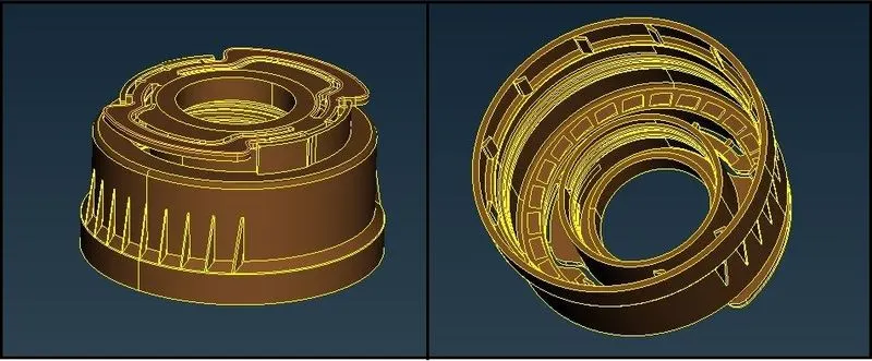
Purpose of this paper is to
- Perform topology cleanup for geometrical errors
- Creation Midsurface from the 3D Plastic Bottle Cap model
- Assign thickness to them as per surface thickness by creation of Part set
- Meshing of the 2D midsurface model with required quality criteria
_____________________________________________________________________________________________________________________
Procedure
Geometry Cleanup:
- Import the CAD mode of Plastic Bottle Cap in Ansa.
- Perform check for Geometry.
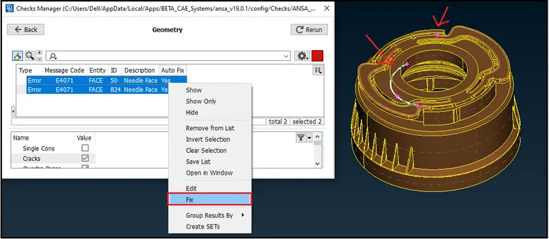
- In above image, we can see some geometrical errors in the model.
- By selecting and applying “Fix”, we remove the errors and can use it for further process.
Midsurfacing:
- After geometry cleanup, we can create Midsurface of a component using “Midsurface” option or we can create Midusrface for each different surface manually.
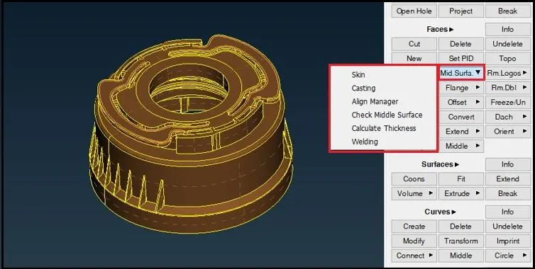
Here in above image we can see that there are different options as per requirement for different types of components to create midsurface automatically.
There are options like Skin, Casting, Welding etc. for automatic Midsurfacing.
So here i basically extracted mid surface by casting process
after extraction process completed in 2 min to 4 min depending upon INTEL PROCESSOR
thereafter I created mid surface if there was missed one by use of middle & fill option , also creating properties by thickness option.