Week - 4 - 2D meshing for Plastic components
Objective:
- Mid surface Extraction of the intricate plastic components.
- Meshing the geometry with the target length of 1 mm.
- Fulfill the quality criteria as per requirements.
The quality criterion to be followed:
|
S.No |
Quality Criteria |
Value |
|
1 |
Target/Average length |
1 |
|
2 |
Minimum Length |
0.5 |
|
3 |
Maximum Length |
3 |
|
4 |
Aspect |
3 |
|
5 |
Warpage |
15 |
|
6 |
Skewness |
45 |
|
7 |
Jacobian |
0.7 |
|
8 |
Minimum Quad Angle |
45 |
|
9 |
Maximum Quad Angle |
135 |
|
10 |
Minimum Tria Angle |
30 |
|
11 |
Maximum Tria Angle |
120 |
|
10 |
Tria Percentage |
15 |
ABSTRACT: In this challenge, we are going to do the preprocessing step in CAE for a plastic component which are having varying thicknesses. The geometry which is taken is a plastic bottle cap which is very much intricate, therefore we need to study geometry very well in order to extract the middle surface and meshing. The main intension of doing this challenge is to learn to mesh plastic components as many components used in the automobile are made of plastic to compensate for weight /strength.
METHODOLOGY:
- Import geometry
- Topological error cleanup
- Mid-surface extraction
- Quality criterion setup
- Meshing and Mesh improvement.
PROCEDURE:
Geometry importing and topological cleanup
After Importing geometry, study geometry carefully. Do the geometry check. Resolve the issues/errors. To study geometry and refine the resolution we will alter the shell length by switching to the mesh mode and going to length block under the section of the perimeter and assigning value as 1 for both macros as well as for perimeter.
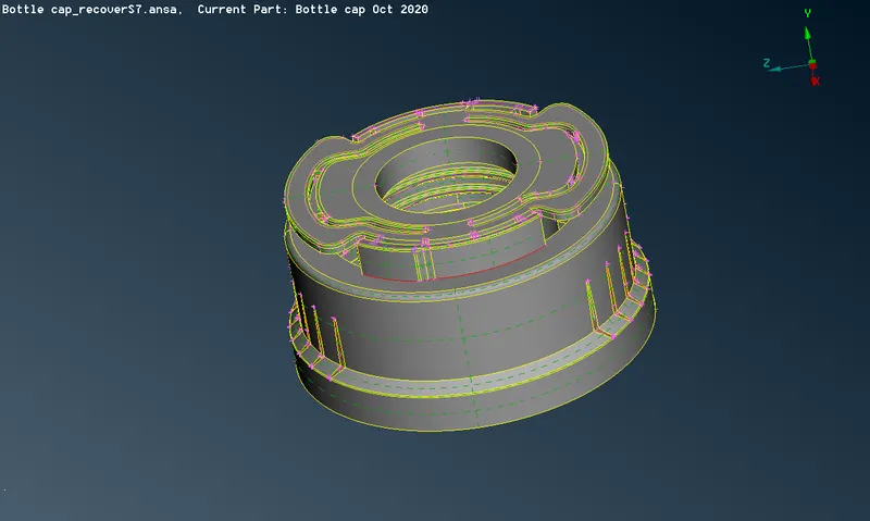
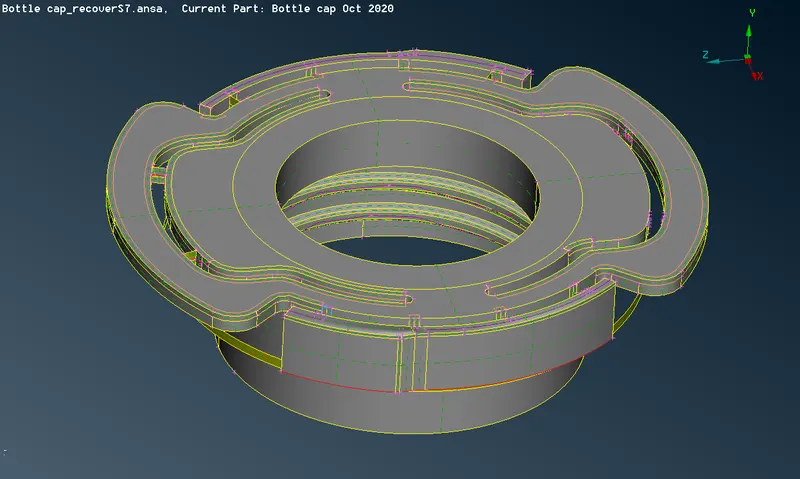
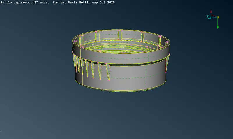
This will help to visualize the geometry very well for further Mid surface extraction.
Before we start taking mid-surface we should measure the thickness all over the geometry. doing so will help us to assign them under different property IDs. So there are a total of 21 different thicknesses measured in this geometry and they all must be addressed separately with different property ID's.
MID-SURFACE GENERATION:
Now for generating mid surface we have multiple options such as
- Auto- mid
- Manual offset
- Middle
while using Auto mid the ANSA crashes and fails to generate the mid surface. so we will go with the manual mid-generation method i.e. using offset and middle options. you can get these options under the faces section.
Note: under the middle option there are two options single and multi. we can use them differently depending on the shape of the geometry.
Areas hard to take mid surface
1) Threads section: used curve middle option to create curve along the surface and then generate new surface using New->Coon and extending them to the ring middle wall behind it.
2) Compression fit blocks: In order to take the feature we have to approximate and compromise the mid surface by offsetting the face in the middle(as shown below)
3)Ribs and fins: create the curve on the surface of the ribs. Hide the parent geometry and generate a new face enclosed by the curves as shown below and after confirmation extends the surface to another midface.
4) As addressed earlier feature with multiple thicknesses, so for taking mid surface we will split the feature into 3 parts such that we can assign different properties to them.
Final Mid surface:
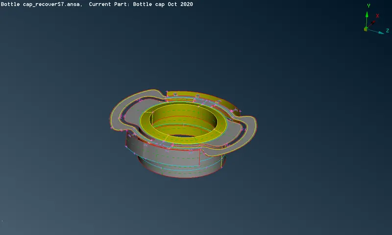
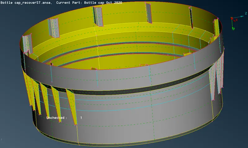
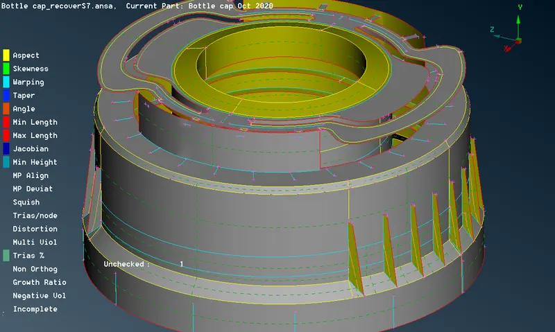
Assign all the quality parameters and mesh parameters.
assign the target length as 1 mm and minimum and maximum length as 0.5mm and 3 mm.
Meshed model:
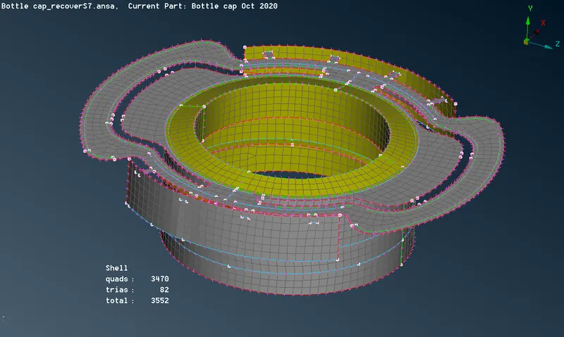
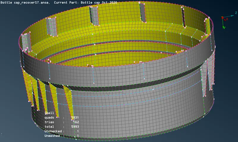
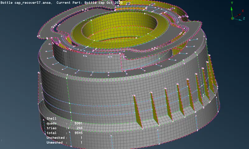
Some elements fail with respect to quality parameters. The major OFF regions are:
1) This area fails majorly because of minimum length, skewness & aspect ratio. As the elements crushed between the stitched construction line and projected triple con of thread extended on the surface.
2) The intersection of the triple con (fail due to minimum length)
It is not possible to resolve these issues due to geometric constraints so we will carry on with this
Learning outcome
- Able to fix topological error
- Able to generate mid surface for any complex plastic geometry with multiple thicknesses.
- Able to set quality parameters and assign properties to different thicknesses material.
- Able to understand and implement good practices of meshing any complex geometry.
- Competent in 2D meshing/ shell meshing even for complex geometry by achieving better mesh flow in plastic components.
- Difference between the shell, solid feature, and way to take their mid surface.
Conclusion
From the above challenge, it can be concluded that the methodology for any complex geometry is very similar. In the case of plastic components, we have to make sure that the component should be observed very carefully by taking multiple measurements during mid-surface generation so as to assign them different properties w.r.t their thicknesses. The mesh generated with the help of following good practices is having decent mesh flow and is acceptable for the next step for the solver.