Week - 4
Aim: To write a program in SIMULINK
Objective:
- To Implement the control logic of a “washing machine” using Stateflow as per given sequence:
- If the power supply is available, the system gets activated
- If the Water supply is not available, stop the process & indicate through LED
- Soaking time should be 200s followed by Washing time of 100s.
- Then rinsing happens for next 20s & dryer runs for 50s
After all the processes have completed turn on the finished LED
2. To Make a Simulink chart for the “Gear shift” logic as per below conditions:
Speed Range(kmph) Gear
0 to 15 1
16 to 25 2
26 to 40 3
41 to 60 4
Above 61 5
Give speed input while the simulation is running & display the gear number.
Study 1: Implementing the control Logic of a washing machine
Theory:
A washing machine is a household appliance used to wash laundry. The term is mostly applied to machines that use water as opposed to dry cleaning or ultrasonic cleaners. The working principle of a washing machine is 'Centrifugation'. It is a process that uses the action of a centrifugal force to promote the accelerated settling of particles in a solid-liquid mixture. The washing machine consists if a centrifuge for this purpose. A centrifuge is a piece of equipment that puts an object in rotation around a fixede axis, applying a force perpendicular. to the axis of the spin.
The washing machine consists of the following processes
1. Soaking
2. Washing
3. Rinsing
4. Drying
Model:
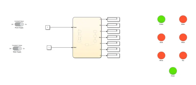
Explanation:
1. For the system to get activated, the power supply needs to be ON. If the power supply is of, we can see that the system is not activated as shown below
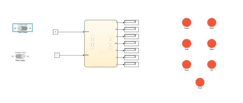
2. Once the power supply is On, the system will get activated and will wait for the water input for the soaking process to start
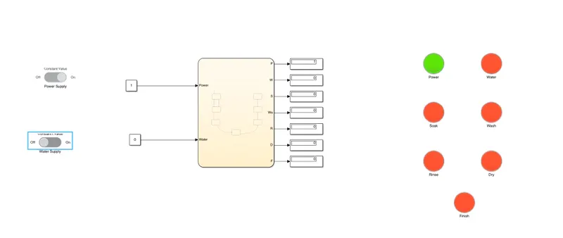
3. Once the water input is provided, the system will follow the state diagram as shown
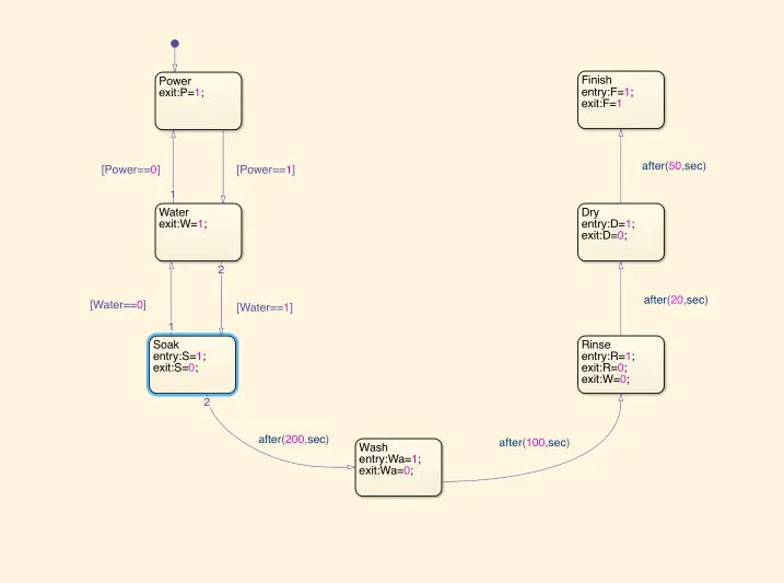
4. As shown above,once the water input is provided, the system will transition into Soak mode. When this state is entered, the variable S will be 1 to notify that this state is going on. After 200 seconds, the system will transition into Wash mode and S=0
5. The next state is Wash state where the clothes are washed. HEre , the variable Wa=1 to notify the state is ON. After 100 seconds the state, Wa=0 and the system will transition into Rinse mode.
6.In the Rinse state, the system will drain out all the water. The variable R=1 will denote that the state is ON and after 20 seconds of rinsing, the system will transition into Dryer mode.
7.The Dry states will tge state where the clothes are dried inside the machine. In this state,the variable D=1 will represent that the state is ON
8. After 20 seconds of Drying, the system will transition into Finish mode to notify the user that all the intended processes of the system are successfully completed.
Result:
Study 2: Making a Simulink chart for Gear Shift Logic as per given conditions
Theory:
A manual transmission is a multi-speed transmission where the gear changes require the driver to select the gears manually depending upon the speed by operating a stick and clutch. The gear shifting mechanism is kept inside a Transmission to provide the uniform torque towards the drive shaft. This is due to the fact that the IC engine produces the optimum torque only after a certain speed and drops again. So in order to achieve optimum torque, we make use of the transmission to manipulate the Torque provided
The alternative to a manual transmission is an Automatic transmission: common tpyes of the automatic transmission are the hydraulic automatic transmission, automated manual transmission, dual-clutch transmission and the continously variable transmission
Model:
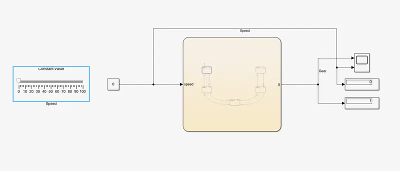
Explanation:
1. To simulate the speed of the vehicle, we use the Slider block to input the speed of the vehicle at any given time. W connect the slider to a constant block an provide it as the input to the chart.
2. Once the Vehicle speed is provided, the process flow can be seen as shown below.
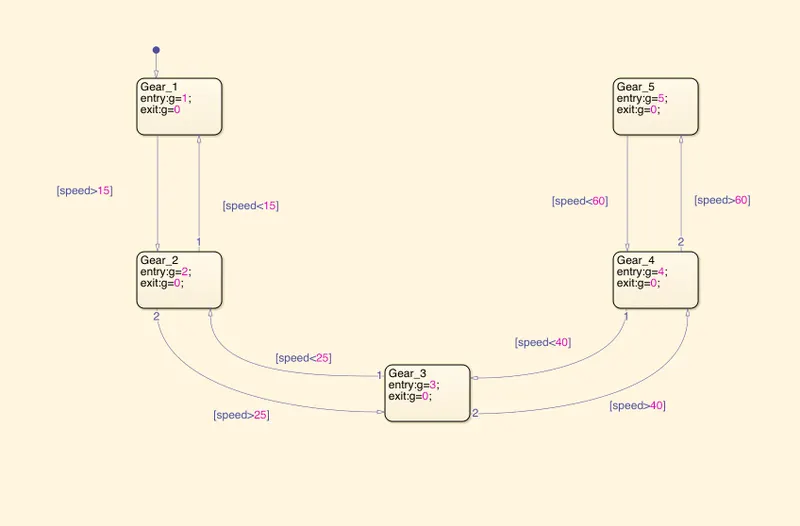
3. We have defined the gears 1,2,3,4,5 as 5 sperae transition blocks
4. To shift from one state to another, the speed condition of the vehicle needs to be achieved for the transition to take place.
5. As we have defined the gear to be changed as per the vehicle speed, the output 'g' will display what gear the vehicle is in at that particular speed.
6. The results of the simulation can be seen below
Results:
When Speed < 15
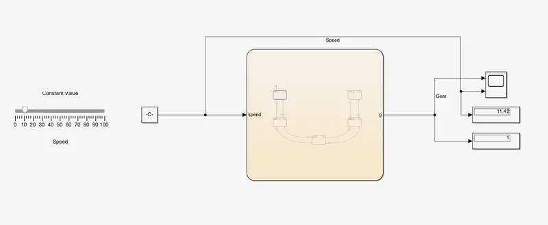
When Speed is between 16 & 25 kmph
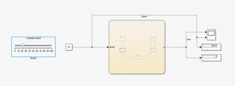
When Speed is between 26 & 40
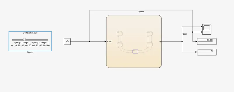
When Speed is between 41 & 60
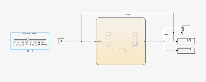
When Speed > 61
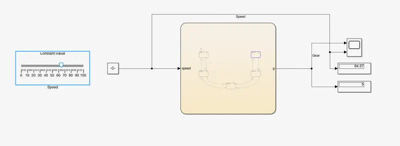
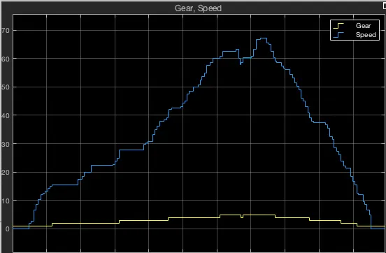
We can see from the above graph that gear changes as per the speed of the vehicle.