Week - 4
CHALLENGE-1: CONTROL LOGIC OF A WASHING MACHINE
AIM: To implement a control logic of a washing machine using simulink stateflow as per the given sequence.
GIVEN SEQUENCE:
- If the power supply is available, the system gets activated
- If the Water supply is not available, stop the process & indicate through LED
- Soaking time should be 200s followed by Washing time of 100s.
- Then rinsing happens for next 20s & dryer runs for 50s
After all the processes have completed turn on the finished LED.
MODEL WITH OUTPUT:
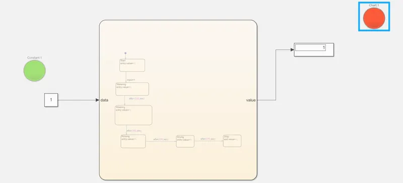
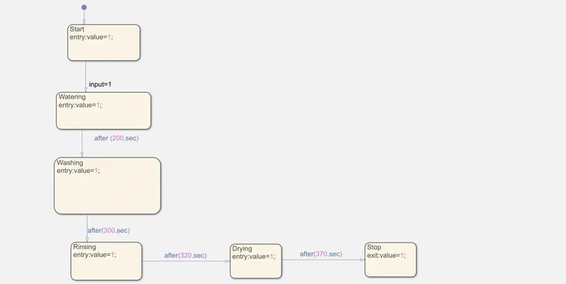
EXPLANATION:
- First open a new model in simulink window and search for 'chart' which is used to create a flow chart of the control logic for the washing machine as per the given condition/sequence.
- Inside the chart window by clicking on the state icon we can create the state blocks.
- After,creating of the state blocks we have to put or write the state name as mentioned in the flow chart diagram 'START','WATERING','WASHING','RINSING','DRYING','STOP' are actually the state names,which represents the operation or process happening at the states.
- Conditions,which we have to give in the state blocks for the flow of the process by the means of input,which actually drive the process flow or the flow chart.
- By joining of all the state blocks,we can actually assing which state is going to run after a state in a continous flow.
- Condition for the states,the conditions which we are giving in the joing of states is actually runs the states after a certain time or a certain condition,which we are giving to it.
- For,Starting of the process a lamp is shown in green color which indicates the process has started and while finishing a red lamp is used to indicate it,by linking the lamp with the regarding input and output datasets.
CHALLENGE-2: GEAR SHIFTING LOGIC
AIM:
To make or create a Gear shifting logic using flow chart in simulink as per the given conditions.
GIVEN CONDITION/STATE:
Speed Range(kmph) Gear
0 to 15 1
16 to 25 2
26 to 40 3
41 to 60 4
Above 61 5
Give speed input while the simulation is running & display the gear number.
M0DEL:
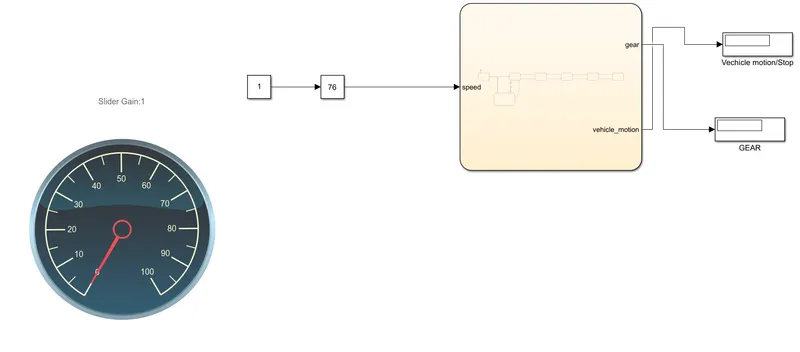
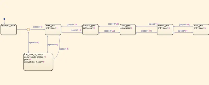
EXPLANATION:
- In this above model,the same steps follows to create a model and in the chart window we have to give the states and its conditions as per the given condition.
- We are just creating the states as first gear,second gear,third,fourth and fifth gear as per the given codition.
- And,giving the flow condition for the state as means of speed like,'speed>16',etc.,.So, actually we are defining the gear condition by the speed input.
- By using the SLIDER GAIN block with the running time infinity we can increase and decrease the speed.
- By using the DISPLAY block we can see at which speed which gear is shifted or changed according to the up/down of speed.
OUTPUT:
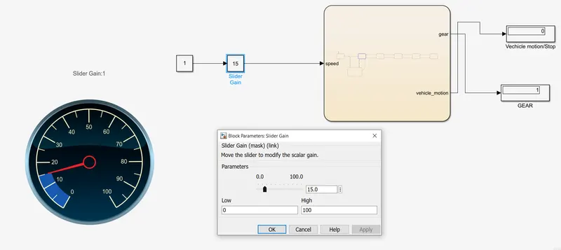
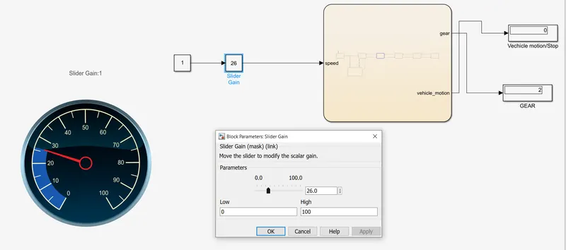
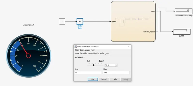
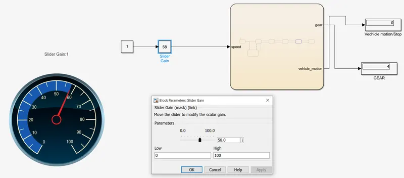
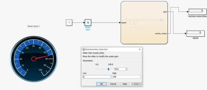
THE ABOVE OUTPUTS ARE SHOWING THAT FOR DIFFERENT SPEED INPUT THE GEAR CHANGES AUTOMATICALLY AND DISPLAYED WHICH GEAR IS SHIFTED IN THE DISPLAY BLOCK.