Project
BAJA ATV(ALL TERRAIN VEHICLE) CVT REPORT
AIM:
To make/create a technical report of the BAJA ATV CTV model by carry out a system level simulation on it.
MODEL:
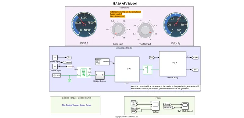
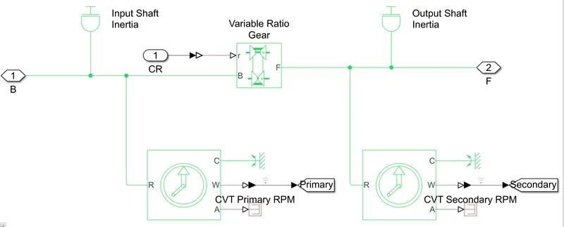
INSIDE THE CVT BLOCK:
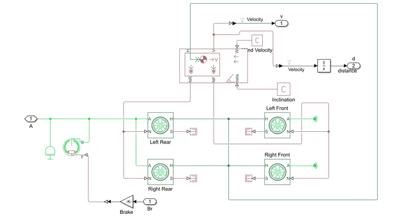
INSIDE THE VEHICLE BODY BLOCK:
Blocks used:
- Signal builder
- Go to
- Generic engine
- Rotational motion sensor
- Simple gear block
- Variable rotation transmission block
- Inertia blocks
- Vehicle body block
- Tier block
- Constant
- Mechanical rotational reference
- Solver configuration
- From
- Scope
- Double shoe brake
- Integrator
- PS-Simulink converter
- Simulink-PS converter
- PS Terminator
- PS constant
EXPLANATION OF THE MODEL/REPORT:
First of all……What is BAJA?
The BAJA, is an Event which is held in US for every year with international participants. It is a Mexican off-road motorsport race held each year on the Baja California Peninsula. The BAJA allows various types of vehicle classes to compete on the same course with classes for cars, trucks, motorcycles, ATVs and Buggies. Since last year BAJA has organized its sub-event called BAJA-SAE in INDIA in pithampur MP. And, SAE Stands for Society of Automotive Engineers.
- The data’s for the model is actually received from/given by the BAJA team like Torque, speed ratios, dimensions of the vehicle, etc.
- Signal Builder block is used to give the input of Throttle and brake to the engine of the BAJA ATV.
- A Generic engine block is used as a engine of the vehicle model and the inputs which is actually an image format as shown below,
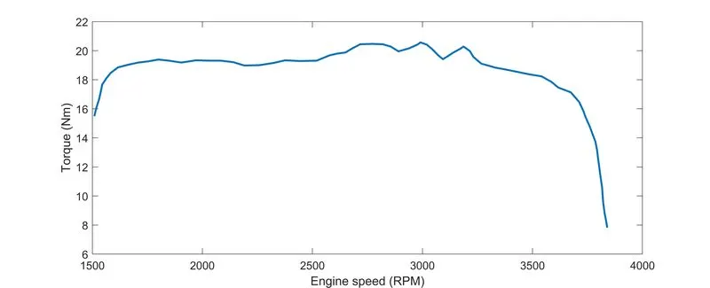
- The data’s from the image we can actually extract it using the matlab FILE EXCHANGE called GRABIT, Which will extract the exact data points from the image file.
- The Next component of the vehicle model is CVT (Continuous Variable Transmission) block, in that for the Primary and Secondary Shafts we have used the Inertia blocks.
- In the CVT, Speed reduction will occurs when the variator of the Secondary shaft moves inwards and the overdrive takes place when the variator of the Primary shaft moves inwards. As shown in the image,
- So we are using the VARIABLE RATIO TRANSMISSION block in the CVT and connecting the INERTIA blocks to it, which will actually represents the primary and secondary pulley.
- And, to connect the CVT with the engine we need some speed reductions that’s why we are using the SIMPLE GEAR.
- Further, we are having the vehicle body sub-system which is actually have VEHICLE BODY block. In this we can change the dimensions of the vehicle body, No. of wheels in each axels, vehicle mass and we can also change the drag co-efficient too.
- TIER block, which represents the tire and wheel drum of the vehicle model with the DOUBLE SHOE BRAKE block, which will be used to apply break to the vehicle if needed.
- After running the simulation for 200sec the result comparisons As follows,
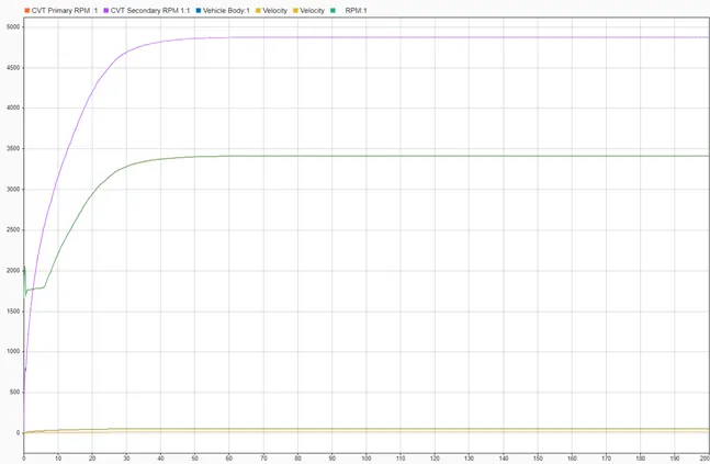
simulink data inspector
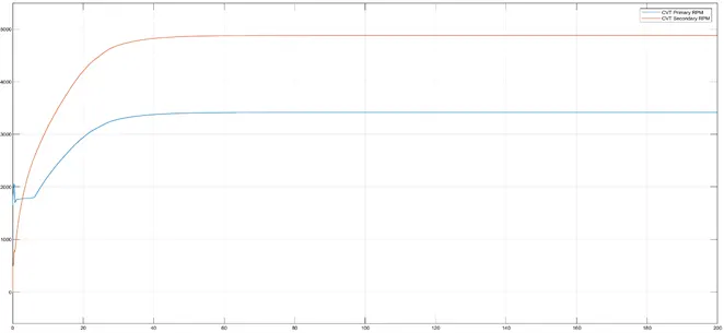
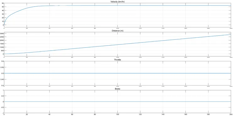
- The above results are showing the RPM range of the Primary and secondary shafts with a constant throttle input and with no brake applied.
- By observation the velocity is raised gradually and got constant at a same input with the vehicle mass.