Week - 4
1.Control logic of washing machine:
Steps for stateflow:
a) To run the operation of sequence of washing machine.We need to create a Stateflow chart to perfom the sequence in allocated time.
b) As per condition,the power supply is avilable,if system gets started.
c) To start a machine,we need to provide a input signal using a constant block with values as ''1'' defines the ON state,where as ''0'' defines the OFF state.
d)And for the water supply,we need to Provide a constant block, same defines as power supply,''1" defines the ON state,where as ''0'' defines the off state.
f) A lamp block is used to display all the opeartion and colour is assigned to respective operations of lamps.
by varying the simulation time,we can check the LED colour.
g)A display is used the Present status of Each condition.
STATEFLOW LOGIC FOR WASHING MACHINE:
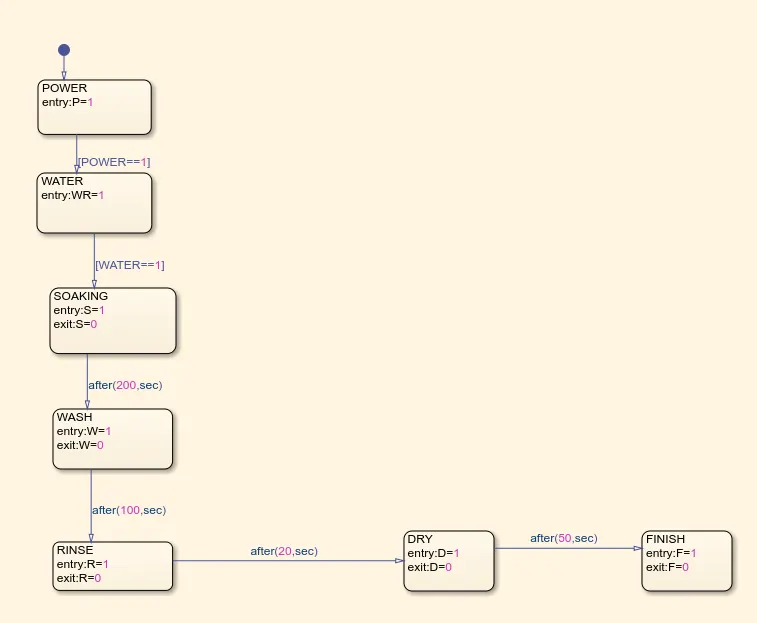
SIMULINK MODEL:
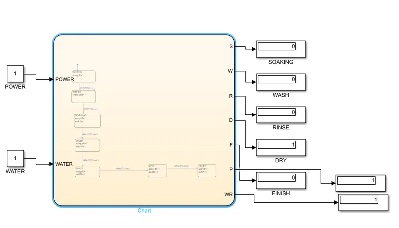
RESULT:
Condition 1:Power supply=0,water supply=0,then lamp is in red colour,it indicates system is in Off condition.
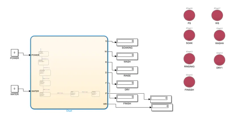
Condition 2;
In this state power is assigned as 1,where as water supply remians 0.the power generated and in displays as 1 and lamp is in green light.
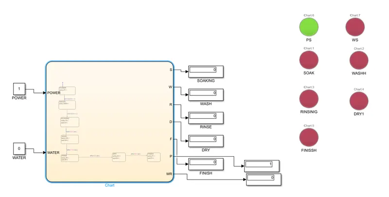
Condition 3:
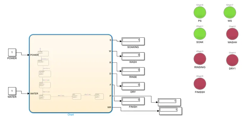
Both power&water supply values are Given as 1.Simulation is done for 200 sec,where soaking process is completed.
Condition 4:
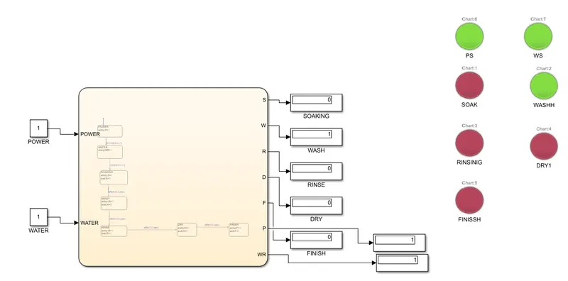
Simulation is done for 300 sec,The Wash process is completed.
Condition 5:
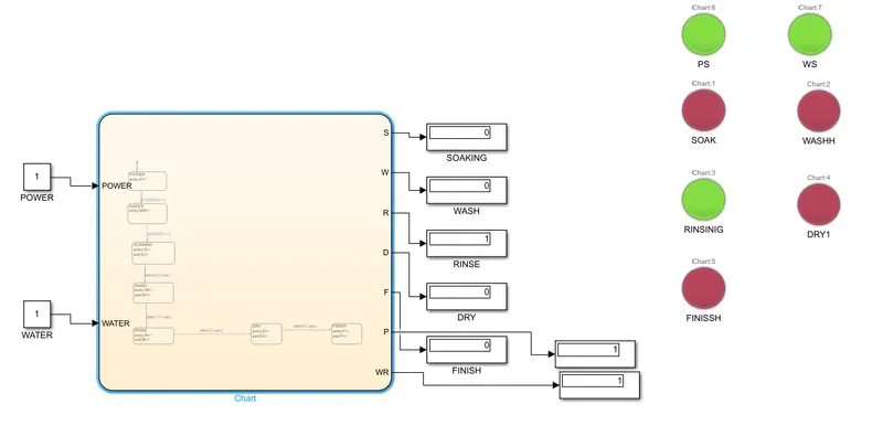
Simulation is done for 320 Sec,Where is Rinse process is completed.
Condition 6:
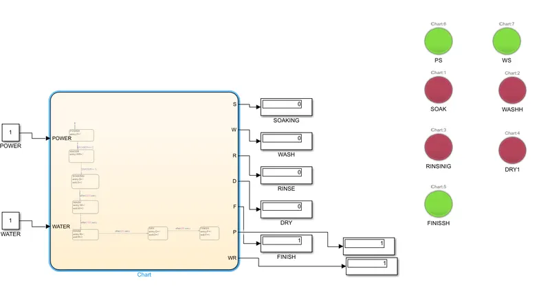
Simulation is Done for 400sec,Where Dry and finish Process complated.
2.Gear shift stateflow model:
Simulink model:
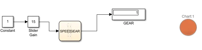
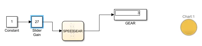
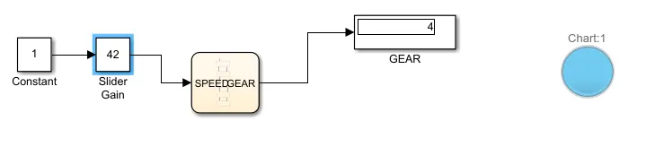
In this model,inputs are generated by slider gain,which is connected to constant block 1.
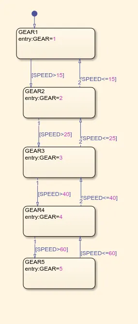
The Gear shifted is acted as conditions in state flow.
The Gear is Shifted by variations in speed.
The Gear Range are created in chart as several gear system.
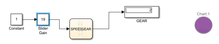
display block is used to obtain result.
Stateflow model:
Slider gain:
Speed is given as input in slider gain for Gear Shift variations.
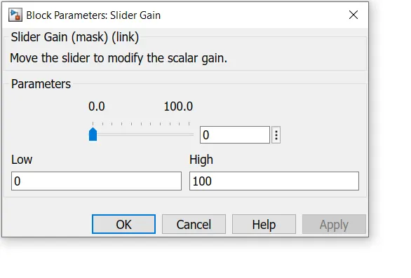
If Constant value is 1,and Slider Gain value is 0,then the Gear is in Neutral Condition.

When Speed range is 0 to 15,Gear 1 is proceed,output 1is displayed.
When speed range is 16 to 25,gear 2 is proceed,output 2 is displayed.
When Speed range is 26 to 40,gear 3 is proceed,output 3 is displayed.
When Speed range is 41 to 60,Gear 4 is procced,output 4 is displayed.
When speed range is above 60,Gear 5 is proceed,output 5 is displayed.

Conclusion:
Thus stateflow model for washing machine and Gearshift is Created and executed.