Project 1 (Mini Project on Vehicle Direction Detection
Aim:
To Identify the direction of Vechile Based on Camera input.
Model:
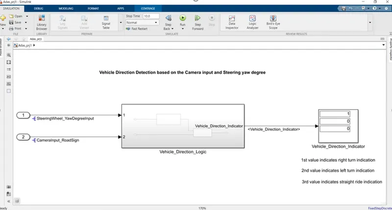
VECHILE LOGIC DIRECTION:
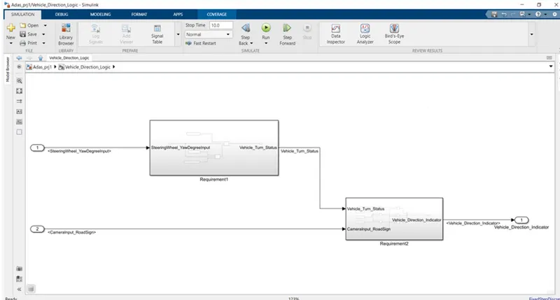
Model 1:
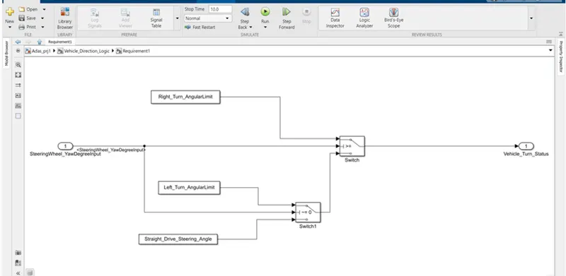
Model 2:
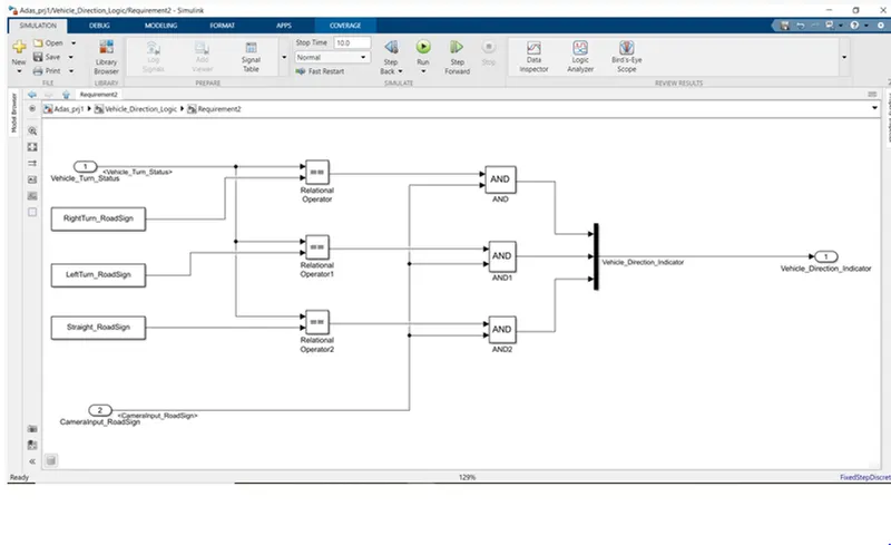
SLDD File creation:
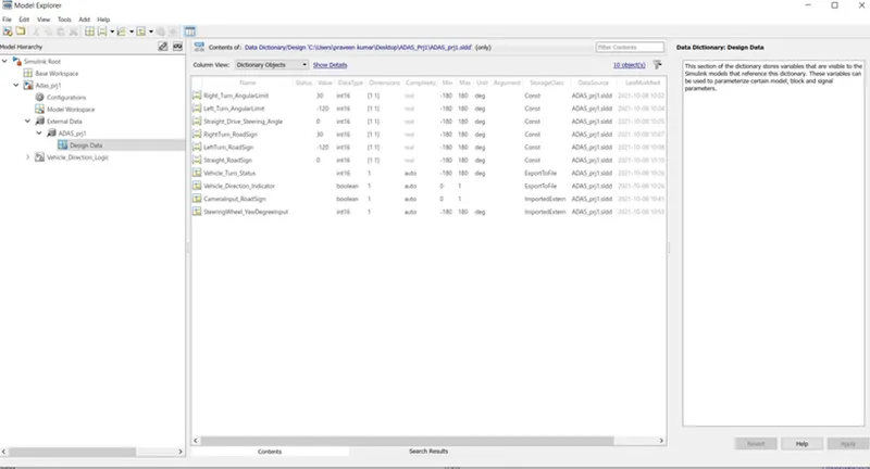
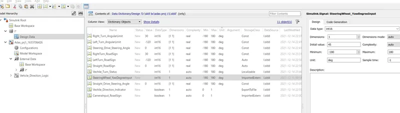
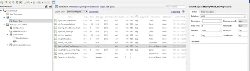
Initially all the input,output signals,calibration values should be get declared for their datatypes,values,storage classes,dimensions,minimum & maximum values and units and link with the model to get access when the model gets simulated.
After declared all the datas in the SLDD file it looks like as shown:
Requirement - 1:
- Steering wheel input as yaw rate (Signal name: SteeringWheel_YawDegreeInput) is the input for this system.
- This is compared against 3 angular values, one each for left turn, right turn & straight drive (Calibration Values: Right_Turn_AngularLimit, Left_Turn_AngularLimit, Straight_Drive_Steering_Angle) to say which specific direction the steering wheel is turning towards.
- Use switch blocks to compare & develop this requirement. Keep this requirement in a subsystem & output of this requirement is a local signal (Signal Name: Vehicle_Turn_Status).
Requirement – 2:
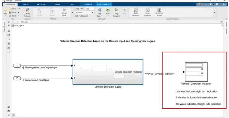
- Keep this requirement as a separate subsystem. Inputs to this requirement are local signal from requirement 1 (Signal Name: Vehicle_Turn_Status) & an input signal from camera (Signal Name: CameraInput_RoadSign), which confirms the occurrence of a road sign.
- Signal Vehicle_Turn_Status is compared against calibration values (Calibration Values: RightTurn_RoadSign, LeftTurn_RoadSign, Straight_RoadSign), if each of them is found equal, then each of the three corresponding output is compared against the camera input signal,
- Using a logical operator block, only one among them is finally given as output signal (Signal Name: Vehicle_Direction_Indicator).
-
Signals resolving:
Here the primary input signals,SteeringWheel_YawDegreeInput and CameraInput_RoadSign are resolved from the SLDD file created by configuring as shown below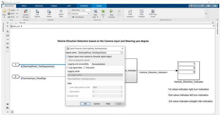
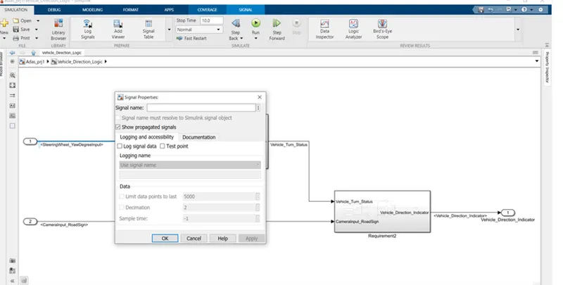
Signal Propagation:
The propagation of these input signal into the subsystems are shown
Model Advisor check:
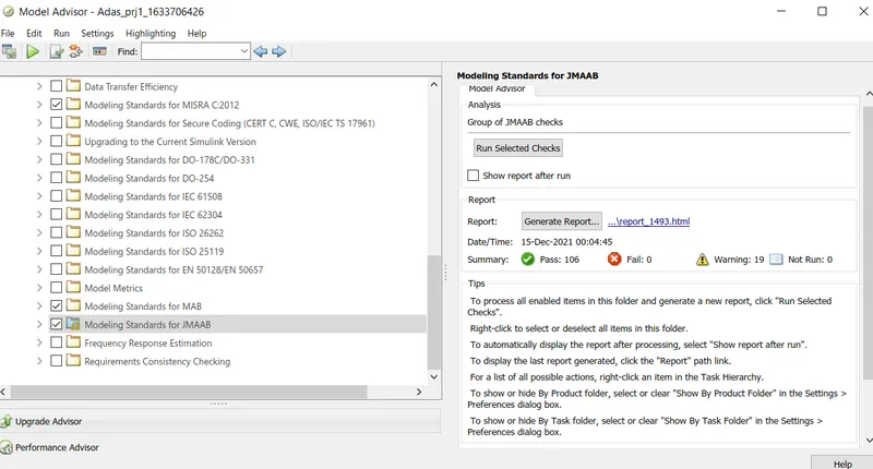
Here its checked for the MAB,JMAB and MISRA C2012 standards using model advisor check tool.
The results are as shown below
Results:
For 45 degree steering yaw angle:
The streering yaw degree given by initial value 45 degree,the result on vehicle direction indicator as
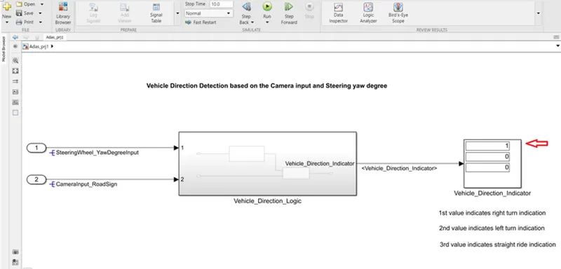
From above result we can see that the Right_Turn indication is activated as 1.
For -120 degree steering yaw angle:
The steering yaw angle given as -120 degree.
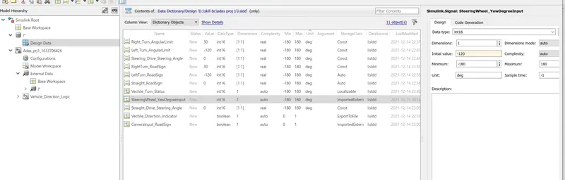
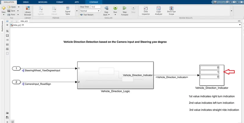
The Left_Turn indication gets activated as 1 and remaining signs are get 0.
For 0 degree steering yaw angle:
Now the steering angle changed to 0 degree.
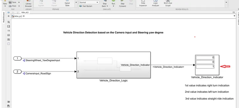
The Straight ride indication gets activated as 1 and other two get as 0.
Thus from these results we had justified our logic for vehicle direction detection based on steering yaw degree and from camera input signs.
Code generation:
#include "Vehicle_Direction_Logic.h"
#include "Vehicle_Direction_Logic_private.h"
/* External outputs (root outports fed by signals with default storage) */
ExtY_Vehicle_Direction_Logic_T Vehicle_Direction_Logic_Y;
/* Real-time model */
static RT_MODEL_Vehicle_Direction_Lo_T Vehicle_Direction_Logic_M_;
RT_MODEL_Vehicle_Direction_Lo_T *const Vehicle_Direction_Logic_M =
&Vehicle_Direction_Logic_M_;
/* Model step function */
void Vehicle_Direction_Logic_step(void)
{
int16_T rtb_Switch;
/* Outputs for Atomic SubSystem: '
/* Switch: '
* Constant: '
* Constant: '
* Inport: '
* Switch: '
*/
if (SteeringWheel_YawDegreeInput >= 30) {
rtb_Switch = Right_Turn_AngularLimit;
} else if (SteeringWheel_YawDegreeInput != 0) {
/* Switch: '
* Constant: '
*/
rtb_Switch = Left_Turn_AngularLimit;
} else {
rtb_Switch = Straight_Drive_Steering_Angle;
}
/* End of Switch: '
/* Outport: '
* Constant: '
* Constant: '
* Constant: '
* Inport: '
* Logic: '
* Logic: '
* Logic: '
* RelationalOperator: '
* RelationalOperator: '
* RelationalOperator: '
*/
Vehicle_Direction_Logic_Y.Vehicle_Direction_Indicator[0] = ((rtb_Switch ==
RightTurn_RoadSign) && CameraInput_RoadSign);
Vehicle_Direction_Logic_Y.Vehicle_Direction_Indicator[1] = ((rtb_Switch ==
LeftTurn_RoadSign) && CameraInput_RoadSign);
Vehicle_Direction_Logic_Y.Vehicle_Direction_Indicator[2] = ((rtb_Switch ==
Straight_RoadSign) && CameraInput_RoadSign);
/* End of Outputs for SubSystem: '
}
/* Model initialize function */
void Vehicle_Direction_Logic_initialize(void)
{
/* (no initialization code required) */
}
/* Model terminate function */
void Vehicle_Direction_Logic_terminate(void)
{
/* (no terminate code required) */
}
/*
* File trailer for generated code.
*
* [EOF]
*/
Result:
Thus the Vechile Direction Detection is made & Verified using Given Values.